| “This site contains affiliate links for which OEMDTC may be compensated” |
NHTSA Campaign Number: 18E085
Manufacturer Allison Transmission, Inc.
Components POWER TRAIN
Potential Number of Units Affected 566
Loss of Drive from Fractured Pressure Switch
A loss of drive can disable the vehicle unexpectedly, increasing the risk of a crash.
Summary
Allison Transmission, Inc. (Allison) is recalling certain H 50 EP, H 40 EP, H 50 Cert, and H 40 Cert Drive Units. The pressure switches on these Drive Units may fail, possibly resulting in a loss of drive.
Remedy
Allison will notify the vehicle manufacturers that purchased the affected transmissions, and dealers will replace the C1 and C2 pressure switches, free of charge. Owners may contact Allison customer service at 1-800-252-5283.
Notes
Owners may also contact the National Highway Traffic Safety Administration Vehicle Safety Hotline at 1-888-327-4236 (TTY 1-800-424-9153), or go to www.safercar.gov.
Revisions to this document are noted by a stripe in the left-hand margin
2018FA07, Rev. B
September, 2018
SUBJECT: H 40/50 EPTM Drive Unit C1/C2 Pressure Switch
MODELS AFFECTED: H 40/50 EPTM Drive Unit
Introduction:
Allison Transmission, Inc. (ATI) has identified an issue with the pressure switch (P/N 29506484) used in a specific population of H 40/50 EP Drive UnitsTM. The Drive Units, within the serial number range specified below, were built with pressure switches that can fail in an either open or closed state. The failure can cause diagnostic trouble codes (DTCs) to set which may disable the corresponding clutch, locking the Drive Unit into the unaffected range with reduced performance, or disable propulsion. Additionally, a subset population of Drive Units within the same serial number range may have debris in valve bodies or internal passages that could prevent proper valve operation. The purpose of this Field Action is to proactively replace the two (2) pressure switches used in each of the affected Drive Units, and inspect and remove debris in the subset population according to the procedure included in this Field Action.
Prior to working on vehicles, please read SIL 21-TR-18, Defective Normally Open Pressure Switch P/N 29506484, for parts information. All replacement pressure switches installed in the affected Drive Unit serial number ranges must be stamped with a date code of 1918 or later.
Serial Number Range:
The serial number range included in this Field Action is 7110008855 through 7110009446. All serial numbers in this range will require the two (2) pressure switches to be replaced.
The serial numbers of the subset population requiring the additional debris inspection and removal are 7110009294 through 7110009445.
Repair Process Overview:
All buses equipped with a Drive Unit serial number 7110008855 through 7110009446 will need to have the oil drained into a clean container for reuse. The oil pan will be removed and the two (2) pressure switches replaced. Refer to Allison Electric Drives Service Manual SM3602 Section 5-12 for pan removal and Section 6-15, C1/C2 Relay Valve Body, for switch replacement.
For buses equipped with a Drive Unit serial number 7110009293 through 7110009445, valve bodies will need removed, inspected for debris, and compressed air blown through the C1 and C2 pressure taps in the rear cover to remove any potential debris, followed by pressure switch replacement. Instructions for Drive Unit serial numbers
7110009293 through 7110009445 are provided at the end of this document. Refer to Allison Electric Drives Service Manual SM3602 Sections 5-13 through 5-17 for disassembly and Sections 6-13 through 6-15 for installation.
Table 1. ATI Required Service Parts
| Part Description | Part Number | Quantity Per Bus |
| Pressure Switch, N/O | 29506484 | 2 |
| O-Ring, Switch | 29501439 | 2 |
| Gasket, Oil Pan | 29538847 | 1 |
| O-Ring, Drain Plug | 23019664 | 1 |
| O-Ring, Filter | 23018950 | 1 |
Claim Submittal Information:
For all proactive repairs, refer to Table 2 and Table 3 below for claim submittal information.
For all claims made against repairs that are not proactive; where a pressure switch is already failed before it could be pro-actively replaced, refer to Table 4 and Table 5 below for claim submittal information.
Table 2. Proactive Repair Claim Information
| Claim Type | 04 |
| Special Activity Indicator | 2018FA07 |
| Primary Failed Part | 29506484 |
| Complaint Code | AT02 |
| Failure Code | CC03 |
Table 3. Proactive Repair Labor Codes
| Labor Code | Labor Hours | Labor Operation |
| 00094100 | 1.2 | R&R Oil Pan and Fluid |
| 00096100 | 0.2 | Switch Replacement |
| 00094700 | 2.8 | Debris Inspection |
| 00096400 | 0.5 | Final Test Drive |
Refer to Table 4 and Table 5 below for non-proacitve repair claims.
Table 4. Non-Proactive Repair Claim Information
| Claim Type | 01 |
| Special Activity Indicator | 2018FA07 |
| Primary Failed Part | 29506484 |
| Complaint Code | EL02 |
| Failure Code | AC00 |
Table 5. Non-Proactive Repair Labor Codes
| Labor Code | Labor Hours | Labor Operation |
| 00094100 | 1.2 | R&R Oil Pan and Fluid |
| 00096100 | 0.2 | Switch Replacement |
| 00094700 | 2.8 | Debris Inspection |
| 00096400 | 0.5 | Final Test Drive |
| 00096901 | 0.5 | Troubleshooting and Diagnostics |
Any additional parts, labor, net items, or travel costs deemed necessary to complete this Field Action must be described in detail in the claim narrative. Unexplained costs will be deducted from the claim.
Authorized Allison service outlets must follow the published Allison Transmission current labor time guide for work performed when adding any additional charges.
Procedure for Inspection and Removal of Debris:
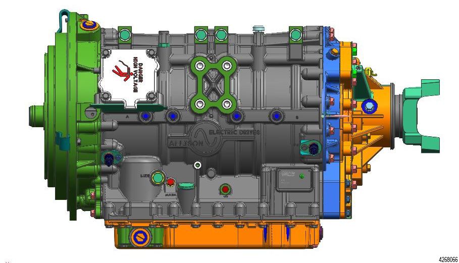
- With the Drive Unit installed, drain the fluid into a clean container for reuse, and drop the oil pan from the Drive Unit.
Figure 1.
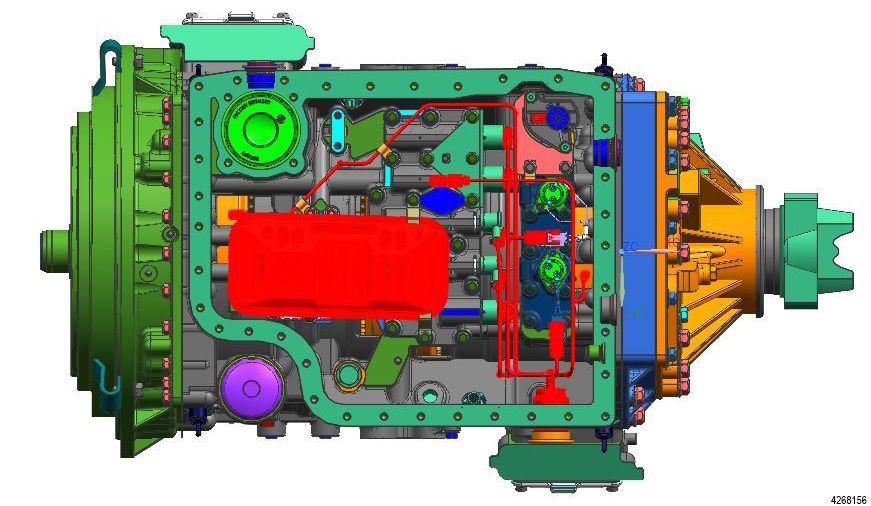
- suction filter and unplug all connectors on the internal harness.
Figure 2.
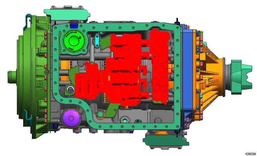
- oil level sensor, C1/C2 valve body, shift relay valve body, control main valve body, and separator plate.
Figure 3.
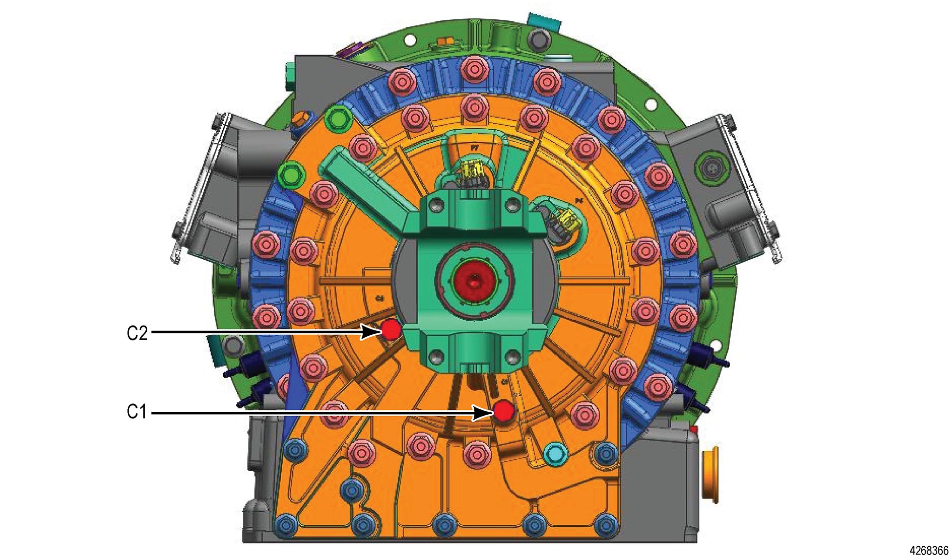
- C1 and C2 plugs (shown below) on the backside of the rear cover.
Figure 4.
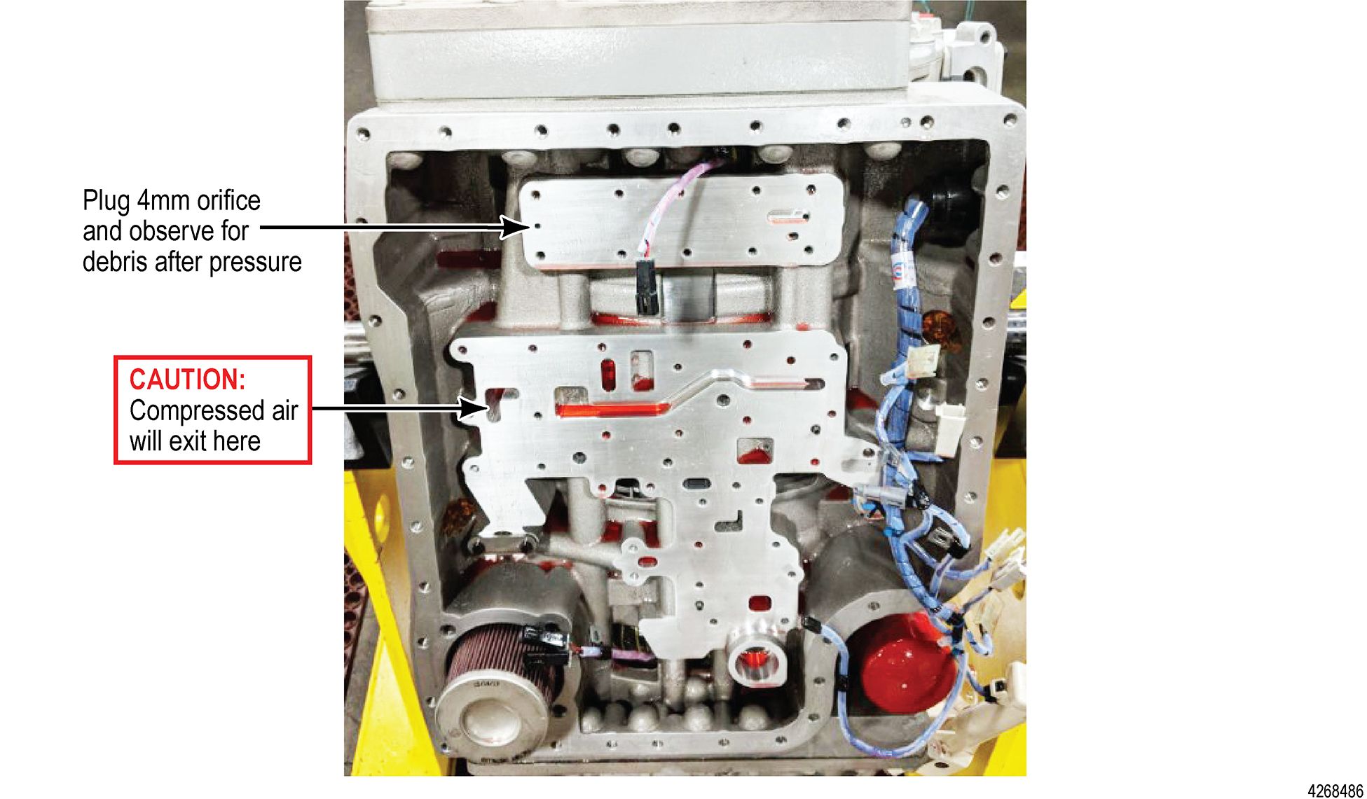
- Starting with the C2 pressure circuit, plug the 4mm orifice on the stator housing, as shown below. Pressurize the C2 pressure tap on the rear cover with air to blow out any debris. Check the previously plugged 4mm passage for loose debris and remove if any is found.
Figure 5.
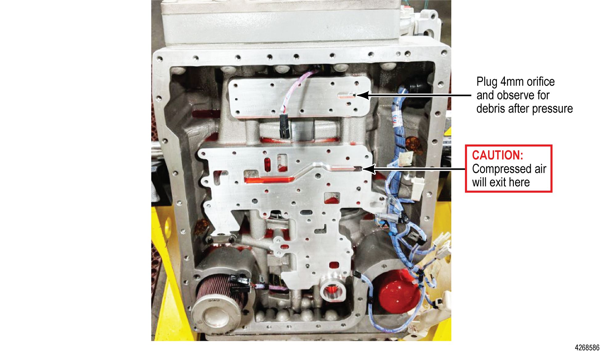
- To inspect the C1 pressure circuit, plug the 4mm orifice on the opposite side the stator housing, as shown below. Pressurize the C1 pressure tap on the rear cover with air to blow out any debris. Check the previously plugged 4mm passage for loose debris and remove if any is found.
Figure 6.
- Inspect the removed valve bodies and the separator plate for any machine chips or debris. Verify proper valve movement. If any debris is found, additional valve body teardown should be performed. Replace any components that may have damage.
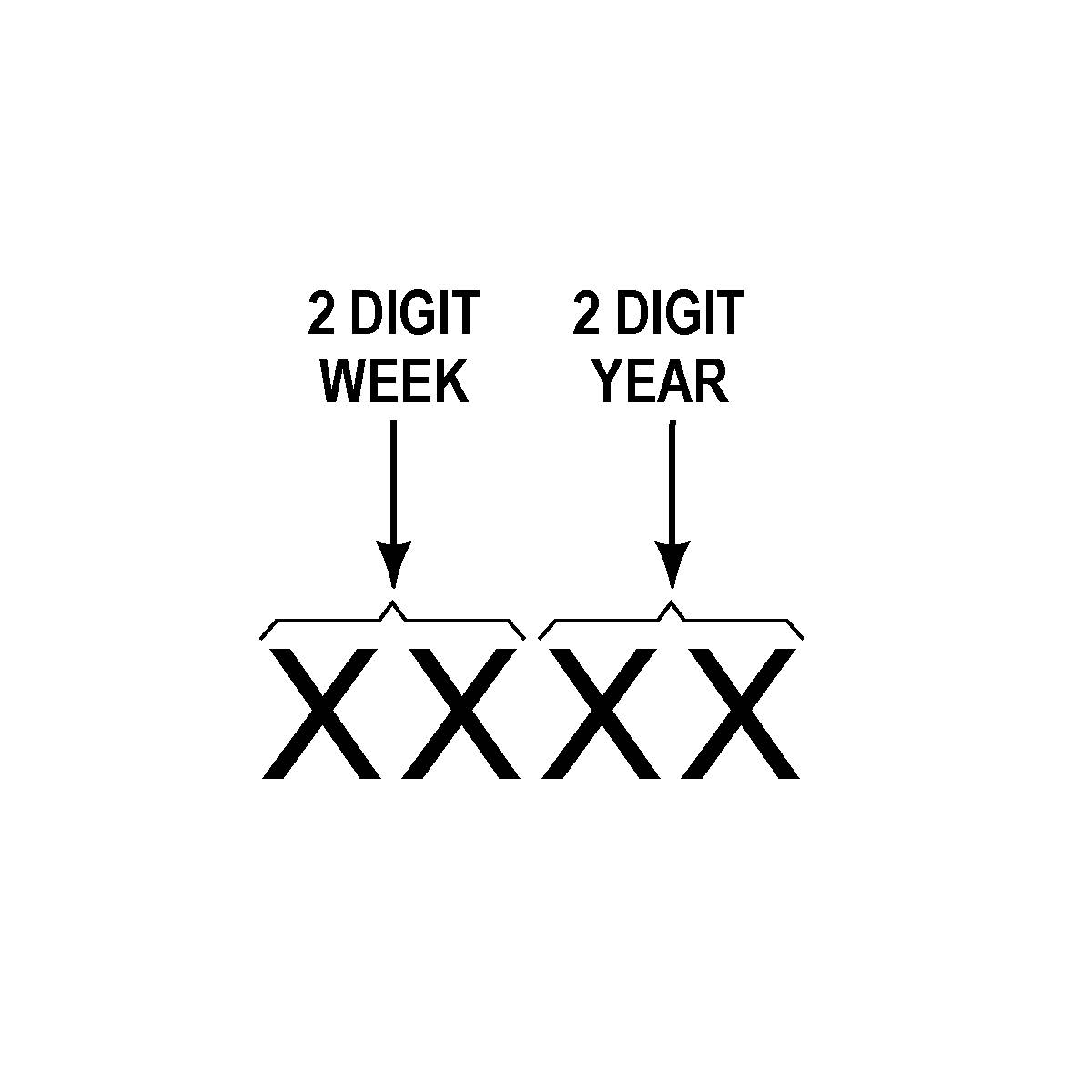
- Reassemble the valve bodies and install two (2) new pressure switches (P/N 29506484) and O-rings (P/N 29501439). New switches must be stamped with date code 1918 or later on the metal retainer ring.
Figure 7. Date Code Format
- Reassemble remaining parts, refill the Drive Unit, and test drive to verify proper operation.
*** IMPORTANT SAFETY RECALL ***
NHTSA Recall No. (18E085)
September ##, 2018
Dear [OEM]:
Allison Transmission Inc. (ATI) has identified an issue with the pressure switch (P/N 29506484) used in a specific population of H 40/50 EP Drive UnitsTM. The affected Drive Units are within the serial number range 7110008855 through 7110009446.Due to an out-of-specification material condition at the pressure switch supplier, the plastic molding used in the switch assembly may fracture. This condition may result in a failure of the pressure switch in either an open or closed state, triggering a diagnostic trouble code. In some circumstances, switch failures in the closed position can potentially disable propulsion at any time during a drive cycle without the ability to regain propulsion, presenting an increased risk of a vehicle accident and/or risk related to offloading passengers in the roadway.
ATI has upgraded the previously released Field Action 2018FA07 to a formal safety recall. (Please refer to Field Action 2018FA07, Rev. A.) A 573 Defect Notification was submitted to NHTSA on August 20, 2018. (Copy attached.)
Attached is a list of serial numbers shipped to [OEM] within the affected range. ATI’s authorized service network will be utilized to replace the C1 and C2 pressure switches used in each affected drive unit at no charge to the customer or [OEM]. ATI expects the repair time to range from 1.2 to 4.0 hours, excluding vehicle and shop logistics.
For drive units installed in vehicles that have left your control, we encourage you to make a safety defect determination in accordance with 49 USC 30118 et seq. and, as appropriate, to submit a Defect Notification to NHTSA in accordance with 49 CFR Part 573. At your option, ATI will conduct the recall, including notifying owners pursuant to 49 CFR Part 577 and performing the remedy.
If [OEM] desires to conduct the owner notification, please advise your ATI OEM Account Manager. ATI would like to review the letter prior to customer distribution. Attached is a copy of ATI’s owner notification letter, which has been approved by NHTSA. If [OEM] would like ATI to handle owner notification, we request the following information be provided no later than September 10, 2018:
- Customer Name
- Mailing Address
- Vehicle Identification Number
- Contact Information
- First Name
- Last Name
- Position
- Phone
Please note that Federal law prohibits delivery of these drive units, or vehicles equipped with these drive units, under a sale or lease until this condition has been remedied.
If there are questions regarding this letter, please direct them to the following main point of contact: Allison Transmission Inc. | One Allison Way | Indianapolis, IN 46222-3271
Larry Hansen
Director, Field Performance Evaluations
larry.hansen@allisontransmission.com
317-242-3712
Regards,
Corey Hudson
OEM Account Manager
corey.hudson@allisontransmission.com
317-756-1426
cc: Copy of ATI’s Part 573 Defect Notification
ATI Owner Notification Letter
2018FA07, Rev. B
September, 2018
 Loading...
2018FA07, Rev. A
August, 2018
 Loading...
Manufacturer Notice
 Loading...
Recall Acknowledgement
September 13, 2018
 Loading...
- Genuine Allison replacement spin-on external filter 29539579 and magnet.
- Allison recommends changing this spin-on filter after initial 5,000 miles of us
- The magnet is required to be changed with the filter to capture possible particulates in oil.
- This Allison genuine spin on filter is one of the most widely used and recommended oil filters for the Allison 1000/2000 transmission.
- Garrett, Steve (Author)
- English (Publication Language)
- 144 Pages - 02/16/2023 (Publication Date) - Sa Design (Publisher)
- Genuine Allison Transmission Filter
- Fits all 2001-2018 GM trucks equipped with Allison transmission
- Fits all vehicles equipped with an Allison 1000, 2000 or 2400 series transmission
- Made in the USA
- Fits Allison 1000, 2000 and 2400 series transmissions
- Castrol TranSynd TES 668 is a premium, full-synthetic automatic transmission fluid specifically formulated for Allison Transmission on-highway automatic transmissions.
- TranSynd 668 provides oxidative stability, anti-wear performance, and friction durability, as well as TES 668 specification differentiators such as extended anti-shudder durability and extended clutch friction durability.
- The Allison genuine spin on filter is one of the most widely used and recommended oil filters for the Allison 1000/2000 transmission.
- 15 Micron Filter
- Improved Fluid Flow & Filtering
- Over 2.5 Times More Filter Surface Area
- Promotes Smoother, More Responsive Shifts
- Step-by-Step Solution to Repair, Overhaul or Rebuild of ALLISON 1000 / 2000 Transmission
- High Quality Charts Available for ALLISON 1000 / 2000
- Valve Body Identification, Electrical Diagrams, Wiring Harness Locations
- Assembly, Dis-assembly, Diagnosis, Troubleshooting, Electronic Controls & Operation
- Very Detailed Explanation For Easy Repair
Last update on 2025-04-17 / Affiliate links / Images from Amazon Product Advertising API
This product presentation was made with AAWP plugin.
