| “This site contains affiliate links for which OEMDTC may be compensated” |
NHTSA ID Number: 10110618
Manufacturer Communication Number: SMB115_B
Summary
Servcie Manual Bulletin – CNG Buses – Pressure Relief Device (PRD) – Torque Requirements & Pressure Regulator – Operating Pressure Range (Revision B)
1 Affected Product
Vehicle
SMB-115B
ISSUE DATE: Jan 09 2014
Pressure Relief Device (PRD) – Torque Requirements
Pressure Regulator – Operating Pressure Range
7 – CNG FUEL SYSTEM
This bulletin identifies the approved torque values for Pressure Relief Devices (PRD) and provides removal and installation procedures specific to the various PRD configurations.
This bulletin identifies the normal operating pressure ranges for the Pressure Regulator used on your New Flyer vehicle.
This information supersedes any prior information on this subject already provided in your New Flyer Manuals. Make this Service Bulletin available to service personnel to inform them of changed information and procedures.
SEOCONTENT-STARTSMB-115B 1 of 8
SERVICE MANUAL BULLETIN
This Service Manual Bulletin is prepared by the Publications Department of New Flyer Industries
Canada ULC. This Service Bulletin supersedes existing information in your New Flyer Service
Manual. Refer to details below.
The New Flyer vehicles described in this manual may be protected by one or more
patents and design applications or registrations in the United States and Canada,
and in other countries. Refer to “Vehicle Patent Information” in this manual.
Copyright © 2014 New Flyer Industries Canada ULC
ISSUE DATE: Jan 09 2014
SMB-115B
APPLICABILITY
VEHICLE LENGTH ???? 30ft. ???? 35ft. ???? 40ft. ???? 60ft. ???? ALL
VEHICLE TYPE ???? High Floor ???? Low Floor ???? Invero ???? Xcelsior ???? ALL
FUEL TYPE
???? Diesel ???? Electric ???? CNG ???? LNG
???? ALL
???? Diesel/Electric ???? Gas/Electric ???? Fuel Cell
SUBJECT Pressure Relief Device (PRD) – Torque Requirements
Pressure Regulator – Operating Pressure Range
SECTION TITLE 7 – CNG FUEL SYSTEM
DETAILS This bulletin identifies the approved torque values for Pressure Relief
Devices (PRD) and provides removal and installation procedures specific
to the various PRD configurations.
This bulletin identifies the normal operating pressure ranges for the
Pressure Regulator used on your New Flyer vehicle.
This information supersedes any prior information on this subject
already provided in your New Flyer Manuals. Make this Service Bulletin
available to service personnel to inform them of changed information
and procedures.
2 of 8 SMB-115B
SERVICE MANUAL BULLETIN
SMB-115B
The New Flyer vehicles described in this manual may be protected by one or more
patents and design applications or registrations in the United States and Canada,
and in other countries. Refer to “Vehicle Patent Information” in this manual.
Copyright © 2014 New Flyer Industries Canada ULC
REVISION INDEX
Rev Description of Change Date
A Original Issue Feb 23 2012
B Included additional PRD part numbers, detailed removal and installation
procedures, and additional torque values for the various PRD configurations
Jan 09 2014
SMB-115B 3 of 8
SERVICE MANUAL BULLETIN
SMB-115B
The New Flyer vehicles described in this manual may be protected by one or more
patents and design applications or registrations in the United States and Canada,
and in other countries. Refer to “Vehicle Patent Information” in this manual.
Copyright © 2014 New Flyer Industries Canada ULC
1. CNG Fuel System
1.1. Purpose
This bulletin is issued to ensure that all
users are aware of:
❒ Differences in pressure regulator settings
as determined by the specific part number
of the unit
❒ Pressure Relief Device (PRD) inspection,
removal, and installation procedures
❒ Pressure Relief Device (PRD) torque values
specific to the part number of the PRD.
1.2. Pressure Regulator Setting
Refer to your New Flyer Parts Manual and
confirm Pressure Regulator part number.
Refer to following chart for correct pressure
regulator setting:
PRESSURE REGULATOR
SETTING
Regulator P/N Pressure
384352 94-120 psi (683-863 kPa)
351934 99-125 psi (683-863 kPa)
336193 99-125 psi (683-863 kPa)
264069 99-125 psi (683-863 kPa)
068540 99-125 psi (683-863 kPa)
065243 99-125 psi (683-863 kPa)
043662 120-150 psi (827-1034 kPa)
057608 120-150 psi (827-1034 kPa)
264070 120-150 psi (827-1034 kPa)
4 of 8 SMB-115B
SERVICE MANUAL BULLETIN
SMB-115B
The New Flyer vehicles described in this manual may be protected by one or more
patents and design applications or registrations in the United States and Canada,
and in other countries. Refer to “Vehicle Patent Information” in this manual.
Copyright © 2014 New Flyer Industries Canada ULC
1.3. Pressure Relief Device (PRD)
1.3.1. PRD Inspection
Pressure relief devices (PRD) are installed
in the vent lines running from each tank.
Earlier tank versions also included a PRD
installed directly in the tank end. All PRD’s
must be connected in a manner that
ensures that the PRD can vent the contents
of the tank regardless of whether the
tank valve is in the closed or open position.
Only quick response PRD’s approved for
use with Lincoln Composites tanks are to
be used with these tanks. Approved
devices are listed in Section 7 of the Parts
Manual for this vehicle. The parts are available
from NFIL Parts Division.
Pressure relief devices are sensitive to
temperature. DO NOT steam clean the
pressure relief devices. DO NOT expose
them to temperatures which exceed
180°F (82°C)
Inspection of the PRD should include the
following:
1. Examine the PRD assemblies for damage.
The PRD assemblies should not be
deformed or show other signs of damage.
Damaged PRD assemblies must be
replaced.
Before depressurizing the container,
ground the venting orifice with a 3-
gauge wire minimum to an appropriate
ground source at least 8′ (2.44 meters)
in the ground. Rapid discharge can
generate a static electrical charge,
which may be sufficient to ignite the
escaping gas. When venting the
container, it must be in a well-ventilated
area free of ignition and heat sources.
DO NOT vent the container in an area
where the flammable gas may
accumulate and ignite.
2. Leak testing of the interfaces between the
PRD and tank or vent lines. These interfaces
should be serviced if any leakage is
observed.
1.3.2. PRD Removal
The following PRD removal and installation
instructions are written to accommodate
the various configurations used, including:
❒ PRD’s installed inline and located near the
solenoid end of the tank. See “Fig. 1: Inline
PRD Installation” on page 5. These PRD’s
will be connected with either tee or elbow
fittings.
❒ PRD’s installed inline and located nearest
the opposite end of the tank. These PRD’s
will be connected to the vent lines with
either straight fittings or, on earlier versions,
with tee and elbow fittings. See “Fig.
1: Inline PRD Installation” on page 5.
❒ PRD’s installed directly in the threaded
boss of the tank end opposite the solenoid
valve. These PRD’s are connected to the
vent line with an elbow. See “Fig. 2: Tank-
End PRD Installation” on page 7.
Use the appropriate removal and installation
procedure to suit the PRD configuration
being serviced.
SMB-115B 5 of 8
SERVICE MANUAL BULLETIN
SMB-115B
The New Flyer vehicles described in this manual may be protected by one or more
patents and design applications or registrations in the United States and Canada,
and in other countries. Refer to “Vehicle Patent Information” in this manual.
Copyright © 2014 New Flyer Industries Canada ULC
1.3.2.1. Removal (PRD with tee/elbow fittings)
1. Defuel tanks. Refer to “Zone Three Venting
Procedure” in your New Flyer Service
Manual for defueling procedure.
2. Remove the PRD located nearest the solenoid
valve as follows:
a. Loosen the Swagelok® fittings and disconnect
vent lines from PRD inlet tee
fitting and outlet elbow fitting and
remove PRD from vehicle. See “Fig. 1:
Inline PRD Installation” on page 5.
b. Loosen the adjustment nut on the PRD
inlet tee fitting and unthread the tee fitting
from the PRD. Discard the O-ring.
c. Loosen the adjustment nut on the PRD
outlet elbow fitting and unthread the
elbow fitting from the PRD. Discard the
O-ring.
Fig. 1: Inline PRD Installation
????????????
????????????????????
????????????????????????????????????
????????????????????????????
???????????????????????? ????????????
????????????????????????????????????????????
????????????????????????????
????????????????????????????????????????????
????????????????????????
????????????????????????????????????
????????????????????????????
????????????
????????????????????????????????????????????????????????????
????????????????
????????????????????????????????????????????????????
????????????????????????????????????
s132501a.svg
6 of 8 SMB-115B
SERVICE MANUAL BULLETIN
SMB-115B
The New Flyer vehicles described in this manual may be protected by one or more
patents and design applications or registrations in the United States and Canada,
and in other countries. Refer to “Vehicle Patent Information” in this manual.
Copyright © 2014 New Flyer Industries Canada ULC
1.3.2.2. Installation (PRD with tee/elbow
fittings)
Ensure directional arrow stamped on
body of PRD is pointing in direction of
flow, toward vent line outlet.
1. Install the tee fitting into the inlet of the
PRD as follows:
a. Fully retract the adjustment nut on the
tee fitting.
b. Lightly lubricate new O-ring with silicone
grease and install against the
backup washer on the tee fitting.
c. Thread the tee fitting into inlet of PRD
until lightly seated.
d. Loosen tee fitting sufficiently to align
parallel with vent lines when installed.
e. Tighten adjustment nut until lightly
seated. Do not final tighten adjustment
nut at this time.
2. Install the elbow fitting into the outlet of the
PRD as follows:
a. Fully retract the adjustment nut on the
elbow fitting.
b. Lightly lubricate new O-ring with silicone
grease and install against the
backup washer on the elbow fitting.
c. Thread the elbow fitting into inlet of
PRD until lightly seated.
d. Loosen elbow fitting sufficiently to align
with vent line when installed.
e. Tighten adjustment nut until lightly
seated. Do not final tighten adjustment
nut at this time.
3. Align the fittings on the PRD, with the vent
lines, ensuring the directional arrow on the
PRD body is pointing in the direction of
flow, toward the vent line outlet.
4. Ensure the vent tubes are fully inserted
within the Swagelok® fittings, and then
tighten the Swagelok® fittings in accordance
with existing instructions in your
New Flyer Service Manual.
ALWAYS tighten PRD fittings to the
torque value specified for the inlet and
outlet location on the PRD. Torque
values for the inlet and outlet fittings
are different and must be adhered to in
order to prevent damage to the PRD
body.
5. Final tighten the adjustment nut on the
inlet fitting with one wrench while holding
the body of the PRD with another wrench.
Torque adjustment nut to specification.
Refer to 1.3.3. “PRD Torque Values” on
page 8 in this bulletin for torque specification.
6. Final tighten the adjustment nut on the outlet
fitting with one wrench while holding the
body of the PRD with another wrench.
Torque adjustment nut to specification.
Refer to 1.3.3. “PRD Torque Values” on
page 8 in this bulletin for torque specification.
1.3.2.3. Removal (PRD with straight
connectors)
1. Defuel tanks. Refer to “Zone Three Venting
Procedure” in your New Flyer Service
Manual for defueling procedure.
2. Remove the PRD located near the end of
the tank, opposite the solenoid valve, as
follows:
a. Loosen the Swagelok® fittings and disconnect
vent lines from PRD inlet and
outlet connectors. Remove PRD from
vehicle.
b. Unthread inlet and outlet connectors
from either end of the PRD and discard
O-rings.
SMB-115B 7 of 8
SERVICE MANUAL BULLETIN
SMB-115B
The New Flyer vehicles described in this manual may be protected by one or more
patents and design applications or registrations in the United States and Canada,
and in other countries. Refer to “Vehicle Patent Information” in this manual.
Copyright © 2014 New Flyer Industries Canada ULC
1.3.2.4. Installation (PRD with straight
connectors)
Ensure directional arrow stamped on
body of PRD is pointing in direction of
flow, toward vent line outlet.
1. Install a new O-ring on the connector and
lightly lubricate the O-ring with silicone
grease. Thread the connectors into either
end of the PRD.
ALWAYS tighten PRD connectors to the
torque value specified for the inlet and
outlet location on the PRD. Torque
values for the inlet and outlet
connectors are different and must be
adhered to in order to prevent damage
to the PRD body.
2. Clamp the wrench flats of the PRD body in
a soft-faced vise and torque the connector
fitting located at the outlet end of the PRD
to specification. Refer to 1.3.3. “PRD
Torque Values” on page 8 in this bulletin for
torque specification.
3. Reverse the position of the PRD in the vise
and torque the connector fitting located at
the inlet end of the PRD to specification.
Refer to 1.3.3. “PRD Torque Values” on
page 8 in this bulletin for torque specification.
4. Install PRD with attached connectors to
the vent lines, ensuring the directional
arrow on the PRD body is pointing in the
direction of flow, toward the vent line outlet.
5. Connect the vent lines to the PRD connectors,
ensuring the vent lines are fully
seated within the Swagelok® fittings, and
then tighten the Swagelok® fittings in
accordance with existing instructions in
your New Flyer Service Manual.
1.3.2.5. Removal (PRD installed directly in end
of tank)
1. Defuel tanks. Refer to “Zone Three Venting
Procedure” in your New Flyer Service
Manual for defueling procedure.
2. Loosen the Swagelok® fittings and disconnect
vent line from PRD elbow fitting. See
“Fig. 2: Tank-End PRD Installation” on
page 7.
3. Loosen the adjustment nut on the elbow fitting
and unthread the fitting from the PRD.
Discard the O-ring.
4. Remove the PRD from the tank and discard
O-ring.
Fig. 2: Tank-End PRD Installation
????????????????????????????????????
????????????????????????????????????
????????????????????????????
????????????????????
????????????
????????????????????????
s132502a.svg
8 of 8 SMB-115B
SERVICE MANUAL BULLETIN
SMB-115B
The New Flyer vehicles described in this manual may be protected by one or more
patents and design applications or registrations in the United States and Canada,
and in other countries. Refer to “Vehicle Patent Information” in this manual.
Copyright © 2014 New Flyer Industries Canada ULC
1.3.2.6. Installation (PRD installed directly in
end of tank)
DO NOT overtighten PRD. Threaded
boss in tank is made of aluminum and
can be damaged if PRD is
overtightened. ALWAYS torque to
specification.
DO NOT apply excessive lubricant to
the O-ring on the PRD. Excessive
lubricant can prevent the O-ring from
sealing properly. Use only a minimal
amount of lubricant on the O-ring.
1. Lightly lubricate the new O-ring with silicone
grease and ensure it is properly
installed in the O-ring groove of the PRD.
2. Install the new PRD into the threaded boss
of the tank and torque to 90 to 110 ft-lb.
(122 to 149 Nm).
3. Install the elbow fitting into the outlet of the
PRD as follows:
a. Fully retract the adjustment nut on the
elbow fitting.
b. Lightly lubricate new O-ring with silicone
grease and install against the
backup washer on the elbow fitting.
c. Thread the elbow fitting into PRD until
lightly seated.
d. Loosen elbow fitting sufficiently to align
with vent line when installed.
e. Tighten adjustment nut until lightly
seated. Do not final tighten adjustment
nut at this time.
4. Align elbow with vent line and insert vent
line into fitting until fully seated.
5. Tighten the Swagelok® fitting in accordance
with existing instructions in your
New Flyer Service Manual.
6. Final tighten the adjustment nut on the
elbow.
1.3.3. PRD Torque Values
PRD TORQUE VALUES
PRD P/N Torque
048919 Inlet Fitting – 35 to 45 ft-lb.
(47 to 61 Nm)
Outlet Fitting – 35 to 45 ft-lb.
(47 to 61 Nm)
069774 Inlet Fitting – 35 to 45 ft-lb.
(47 to 61 Nm)
Outlet Fitting – 15.8 to 17.5 ft-lb.
(21.4 to 23.7 Nm)
098252 Inlet Fitting – 35 to 45 ft-lb.
(47 to 61 Nm)
Outlet Fitting – 15.8 to 17.5 ft-lb.
(21.4 to 23.7 Nm)
069837 90 to 110 ft-lb. (122 to 149 Nm)
098277 90 to 110 ft-lb. (122 to 149 Nm)
SMB115_B
 Loading...
| “This site contains affiliate links for which OEMDTC may be compensated” |
- 【TWO MODES】: The 1/2 PSI gas regulator have both propane and natural gas mode. The factory setting of the nature pressure regulator is propane mode, if you need natural gas mode, please open the knob on the cover to convert the screw to natural gas mode, please refer to our picture for details.
- 【SPECIFICATIONS】:The therad on the Regulator is 1/2" Male Thread and the end of house is 3/8" Female Flare. When using LPG regulating valve: LP inlet pressure is 2.74Kpa(11 "w.c), outlet pressure is 2.45~2.55 kpa(10 "w.c), gas flow rate is 30L/min; When using natural gas regulating valve: LP inlet pressure is 1.74Kpa(7 "w.c). Outlet pressure is 0.95~1.05 kpa(4 "w.c), flow rate is 50L/min.
- 【FUNCTIONS】: This 102-B model rugulator converts your equipment that uses propane to one that uses natural gas. You can use it to replace the Kitchen Aid Natural Gas Conversion Kit 710-0003.Functions the same as the original part contents.
- 【CONVERSION MODEL】: This natural gas pressure regulator can converts these KitchenAid grill models to NG: 720-0709, 720-0709B, 720-0709C, 720-0733, 720-0733A, 720-0745, 720-0745A, 720-0745B, 720-0787, 720-0787D, 720-0819, 720-0819A, 720-0891B, 720-0826, 720-0891R, 720-0893.
- 【WARM TIPS】: The natural gas conversion Kit is rated to operate from -32°F to 225°F (0°C to 107°C) Do not install the regulator too close to heating equipment or use it in very cold environments. Heat and cold will change the resistance of the spring inside the regulator. The gas pressure regulator will not shut off the gas flow.
- 100% brand-new, never ever been utilized, all parts are tested and quality controlled prior to shipment.
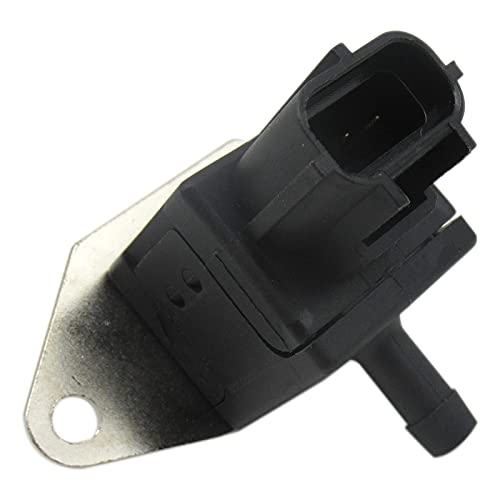
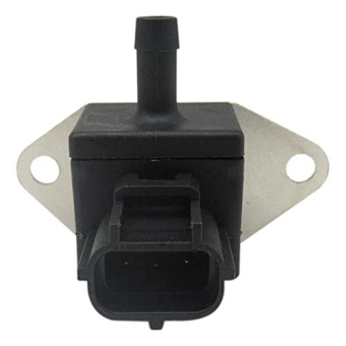
- Manufacturer Part Number:FPS7, 3R3Z-9F972-AA, 3R3Z-9F972-AB, 3R3Z9F972AA, FPS-7; 3R3Z9F972AB, 3R3E-9F972-AA, F8CZ-9F972-BD, F8CZ-9F972-BC; F8CZ-9F972-BE, 3R3E9F972AA, F8CZ9F972BD, F8CZ9F972BC;XW4Z-9F972-BA, XW4Z9F972BA, 3R3Z-9G756-AC, F8CZ9F972BE; 3R3Z9G756AC, F8CF9F972BG, F8CF9F972BE, F8CF9F972BH; F8CF9F972BF, F8CF-9F972-BE, F8CF-9F972-BH;FPS17, FPS-507, F8CF-9F972-BF, F8CF-9F972-BG;PR244, SU10479, SU13804, 5G1142, 5S9017, FPS507, FPS-17.
- Fits For Ford
 Lincoln
 Mercury
 Vehicles with 2.0 2.3 3.0 3.8 3.9 4.6 5.4 Liter V6 V8 L4 Engine : For 2004 2005 Ford
 Explorer; For 2003 2004 Ford
 Crown Victoria; For 2004 2005 2006 2007 2008 Ford
 F150; For 2000 2001 2002 2003 2004 Ford
 Focus; For 2005 2006 Ford
 E150 Club Wagon E250 GT; For 2002 2003 2004 2005 2006 2007 Ford
 Taurus Thunderbird.
 - Fits For 1999 2000 2001 2002 2003 2004 Ford
 Mustang
 ; For 2003 2004 2005 2006 Lincoln
 Town Car Aviator; For 1998 1999 2000 2001 2002 Lincoln
 Continental
 ; For 2000 2001 2002 2003 2004 2005 2006 Lincoln
 LS; For 1998 1999 Mercury
 Tracer; For 2002 2003 2004 Mercury
 Sable Marauder Mountaineer Grand Marquis
 - Package Include:1x Fuel Pressure Sensor
- 【Brand New】100% Brand New and All parts are tested and quality controlled prior to shipment
- Fitment: Fits For Ford
 Lincoln
 Mercury
 Vehicles with 2.0 2.3 3.0 3.8 3.9 4.6 5.4 Liter V6 V8 L4 Engine : For 2004 2005 Ford
 Explorer; For 2003 2004 Ford
 Crown Victoria; For 2004 2005 2006 2007 2008 Ford
 F150; For 2000 2001 2002 2003 2004 Ford
 Focus; For 2005 2006 Ford
 E150 Club Wagon E250 GT; For 2002 2003 2004 2005 2006 2007 Ford
 Taurus Thunderbird.
 - Fitment: Fits For 1999 2000 2001 2002 2003 2004 Ford
 Mustang
 ; For 2003 2004 2005 2006 Lincoln
 Town Car Aviator; For 1998 1999 2000 2001 2002 Lincoln
 Continental
 ; For 2000 2001 2002 2003 2004 2005 2006 Lincoln
 LS; For 1998 1999 Mercury
 Tracer; For 2002 2003 2004 Mercury
 Sable Marauder Mountaineer Grand Marquis
 - Manufacturer Part Number:FPS7, 3R3Z-9F972-AA, 3R3Z-9F972-AB, 3R3Z9F972AA, FPS-7; 3R3Z9F972AB, 3R3E-9F972-AA, F8CZ-9F972-BD, F8CZ-9F972-BC; F8CZ-9F972-BE, 3R3E9F972AA, F8CZ9F972BD, F8CZ9F972BC;XW4Z-9F972-BA, XW4Z9F972BA, 3R3Z-9G756-AC, F8CZ9F972BE; 3R3Z9G756AC, F8CF9F972BG, F8CF9F972BE, F8CF9F972BH; F8CF9F972BF, F8CF-9F972-BE, F8CF-9F972-BH;FPS17, FPS-507, F8CF-9F972-BF, F8CF-9F972-BG;PR244, SU10479, SU13804, 5G1142, 5S9017, FPS507, FPS-17.
- Package Include:1x Fuel Pressure Sensor
- Function: Prevent water pipes from being damaged due to high pressure, suitable for campers
 , trailers, and RV plumbing systems.
 - Safety: Class C46500 lead-free brass treated by hot casting process technology. Each regulator is tested to contain less than 0.13% lead, well under the NSF/ANSI 372 lead-free requirements of 0.25%, giving you a safe and healthy life.
- Compatible: Designed with 3/4" garden hose thread. It is compatible with all American water sources, easy to use. RVGUARD regulator inlet screen helps to filter out impurities in water.
- Adjustable: Factory Setting: 45 PSI, water pressure setting can be easily adjusted to whatever water pressure you need by turning the screwdriver. Turn clockwise to increase pressure, and turn counterclockwise to decrease pressure.
- Gauge Display: The water pressure can be seen on the gauge, which is necessary for RVs, campers
 , and travel trailers.
- Protects RV/Marine Plumbing: Keep your RV/marine plumbing safe with this brass Camco water pressure regulator. Safeguard against high-pressure city water to protect your hoses & plumbing from potential damage.
- Automatic Pipe Burst Protection: Ensure your pipes are safe using the built-in PSI Guard, preset at 40-50 PSI for automatic burst protection. (Maximum incoming pressure is 125 PSI.)
- Safe for Drinking Water: Camco’s pressure regulator for RV water Hoses is drinking water safe. It’s a must-have camper
 tool for setups that require outstanding water quality.
 - Certified Lead-Free: This water regulator For RV campers
 is crafted from high-quality brass material. It is CSA lead-free content certified to NSF/ANSI 372 & compliant with all federal & state-level lead-free laws.
 - Patented Technology: Expertly crafted, this Patented RV Accessory has undergone extensive testing and quality control to meet the highest standards.
- Thread: 1/4 NPT
- Rated Flow: 19.4 SCFM(550 L/min)
- Temperature Range: 5~60℃(41-140℉), Pressure Range: 7~42 psi
- Aluminum Alloy Material
- When regulating pressure, pull up the rotary knob and rotate clockwise to increase the pressure and rotate anticlockwise to decrease the pressure.
- Adjustable Knob: RVGUARD new design water pressure regulator with an adjustable knob. Just use your hand to adjust the pressure, no tool required, easy to operate. Turn clockwise to increase pressure, and turn counterclockwise to decrease pressure. Factory Setting: 45 PSI.
- Function: Prevent water pipes from being damaged due to high pressure, suitable for campers
 , trailers, and RV plumbing systems.
 - Safety: Class C46500 lead-free brass treated by hot casting process technology. Each regulator is tested to contain less than 0.13% lead, well under the NSF/ANSI 372 lead-free requirements of 0.25%, giving you a safe and healthy life.
- Compatible: Designed with 3/4" garden hose thread. It is compatible with all American water sources, easy to use. RVGUARD regulator inlet screen helps to filter out impurities in water.
- Gauge Display: The water pressure can be seen on the gauge, which is necessary for RVs, campers
 , and travel trailers.
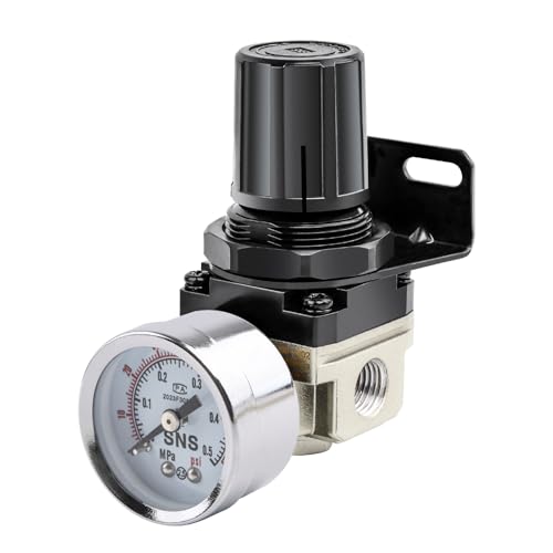
- Materials: plastic, zinc alloy and copper.Female Thread Diameter: 1/4 PT.Maximum voltage: 240V. Maximum current: 15 amps. Maximum pressure: 180 psi, 12 bar.
- Allows precise air control for best painting results with this item.Standard air inlet and outlet are suitable for almost any type of spray paint
- Easy to install and disassemble.With the barometer, can be set and read the data.With the valve knob, you can adjust the atmospheric pressure as needed.Can help save electric power.
- Air compressor pressure switch is a very necessary component to install or connect air compressor or air hoseMain function of valve is to regulate stop and start pressure of air compressor.
- Package List: 1 x pressure regulating valve, 1 x pressure gauge, 2 x connector , 1 x nipple (Double connection) ,1 x Thread Seal Tapes(1/2-394inch)
- Maintains optimum 25 psi pressure and water flow to Drip lines and emitter devices
- Connects to any 3/4" male pipe threaded faucet, garden hose or component
- 20 gallon per minute flow through capacity
- Durable, robust design provides reliable operation
- Constructed of highly durable UV and chemical-resistant materials
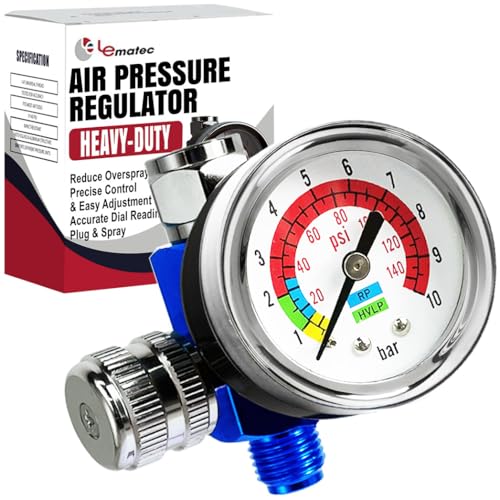
- Precise finishes: Achieve smooth results with our spray gun regulator with gauge, ideal for professionals.
- Reduce waste: Minimize overspray using our HVLP air regulator, saving time and resources.
- Easy control: Adjust air pressure with our inline air regulator, enhancing project control.
- Smooth coating: Ensure even application with our paint sprayer regulator, perfect for all users.
- Stable performance: Trust consistent air pressure with our paint gun air regulator.
Last update on 2025-04-17 / Affiliate links / Images from Amazon Product Advertising API
This product presentation was made with AAWP plugin.
