
Emer™ PRD Replacement for
ElDorado National Bus
CNG Fuel Systems
ENP-736 REV A
June 25, 2020
1. Introduction
Agility Fuel Solutions LLC (Agility®) has determined that pressure relief devices (PRDs) manufactured by Emer™ may fail to operate as designed. This issue has been reported to the National Highway Traffic and Safety Administration (NHSTSA Recall No. 20E-019). Impacted parts include Emer™ p/n PRD2302T-004 (Agility® p/n 10306997) used in Agility® compressed natural gas (CNG) fuel systems produced from October 6, 2016, to April 1, 2020.
PRDs are essential for safe vehicle operation and must be replaced if non-compliant. Agility® personnel have identified fuel system top level part numbers supplied for ElDorado National -California buses containing recalled Emer™ PRDs as original equipment manufacturer (OEM) equipment.
Agility® created this instructional document to guide trained CNG fuel system service technicians in the removal, replacement, and reporting of affected Emer™ PRDs.
1.1. Warning Messages and Symbols used in this document
DANGER
Will cause death or severe injuries if procedures are not followed.
WARNING
Could cause death or severe injuries if procedures are not followed.
CAUTION
Could cause minor or moderate injuries if procedures are not followed.
NOTICE
Practices not related to physical injury. Includes procedures to prevent vehicle damage as well as hints to help an operation or procedure go smoothly.
- A product feature solely used to improve manufacturability or maintain process control ·
- A process parameter or step that has a significant effect on achieving a Critical Characteristic
or Significant Characteristic, or maintaining material identification/traceability.
2. Affected Units
Agility® top level system part numbers as follows:
| 240329-01 – Roofpack, Front | 240329-02 – Roofpack, Rear |
| 240329-03 – Roofpack, Front | 240329-04 – Roofpack, Rear |
| 240329-05 – Roofpack, Rear | 240329-06 – Roofpack, Rear |
| 240329-08 – Roofpack, Rear | 240329-11 – Roofpack, Rear |
3. Tools and Supplies Required
| Fall protection equipment | Safety glasses |
| Safety ladder | Defueling hose with nozzle** |
| NGV1 fuel receptacle adapter* | Microfiber towels |
| Swagelok® preswage tool | 7/8-in. combination wrench |
| 1-in. combination wrench, short† | 1 1/8-in. combination wrench, short† |
| Camera / phone camera | Flashlight |
| Parker® O-lube O-ring lube | Foam mat or tarp |
| Socket wrenches | Swagelok® Snoop® leak detection solution |
| Permanent marker | Agility® reporting form FT.0313 |
| Torque Seal marker | Agility go-nogo gauge, p/n TD 400394 |
| Heat gun | Zip lock bag (NOTE: supplied by Agility with bulk replacement PRD shipment—use for |
| Blue paint marker | PRD return) |
*may be required for defueling on some FMMs
**If not provided at CNG fueling facility
†If short wrenches are unavailable, cut the open end of wrenches down to 6-in. long.
3.1. PRD retrofit kits
Before beginning work, verify proper quantity of correct Agility® PRDs are on hand.
Agility® PRD p/n 10306997 and corresponding fuel system quantities are as follows:
| Agility® fuel system p/n | PRD QTY required |
| 240329-01 | 4 |
| 240329-02 | 4 |
| 240329-03 | 4 |
| 240329-04 | 4 |
| 240329-05 | 4 |
| 240329-06 | 4 |
| 240329-08 | 2 |
| 240329-11 | 2 |
4. Parts Location Identification
Refer to the appropriate fuel system illustration to locate the affected Emer™ PRDs in fuel system plumbing. Figures 1, 2 and 3
Figure 1.
Locations of Emer™ PRDs (1) in front pod fuel system cylinder plumbing. NOTE: Roof pack doors omitted for clarity.
Figure 2.
Locations of Emer™ PRDs (1) in rear fuel system plumbing – three and four cylinder pods. NOTE: Cylinders not shown for clarity.
Figure 3.
Locations of Emer™ PRDs (1) in rear fuel system plumbing – two cylinder pods. NOTE: Cylinders not shown for clarity.
5. Corrective Action / Procedure
5.1. Preliminary Safety Preparation
See PDF Bellow
SEOCONTENT-START
5. Corrective Action / Procedure
5.1. Preliminary Safety Preparation
1
1. Confirm all workers present are wearing appropriate personal protective equipment (PPE) including but not limited to eye protection, gloves, high visibility vests, etc.
2. Set parking brake and secure vehicle with wheel chocks (not shown).
2
Attach a lock and tag (not shown) to block vehicle ignition.
WHAT
WHAT
WHY
Worker safety.
WHY
Prevent vehicle start during repair procedure.
3
Secure a safety ladder in either of the following locations:
A. Inside bus hatch opening
B. Rear of bus exterior
WHAT
WHY
Worker safety.
ENP-736 REV A 6-25-2020 (Printed and downloaded copies are uncontrolled) 7 of 34
4
1. Open fuel system roof pod doors (d).
2. Secure fall protection equipment (not shown) to facilty fall restraint attachment scaffolding.
3. Secure doors open with prop bars (e). Refer to vehicle OEM instructions.
Always reattach fall restraint PPE when resuming work on the roof mount portion of the fuel system.
Cylinder coating is fragile. When working on and around cylinders (f), do not: a) allow objects such as tools to contact cylinders, b) wear hard or sharp edged objects including belt buckles, c) walk or stand on cylinders.
Use a foam mat or tarp to protect cylinders.
WHAT
WHY
Worker safety.
d
e
f
ENP-736 REV A 6-25-2020 (Printed and downloaded copies are uncontrolled) 8 of 34
5.2. Prior to defueling
1
Verify all cylinder valves are open.
WHAT
WHY
Ensure cylinders can be properly defueled.
2
Check fuel system high pressure gauge to verify amount of fuel in the system.
Refer to vehicle OEM operations manual.
IMPORTANT: If vehicle has no fuel onboard, proceed to Step 4.
WHAT
WHY
3
If not already defueled: Defuel bus according to local facility regulations and procedure.
If required: Use defuel hose kit.
Only trained CNG fuel systems technicians may perform defueling.
4
Relieve any remaining system pressure by slowly opening the fuel system bleed valve.
Refer to vehicle OEM operations manual.
WHAT
WHAT
WHY
PRD supply tubes to be removed are pressurized “live” lines.
WHY
ENP-736 REV A 6-25-2020 (Printed and downloaded copies are uncontrolled) 9 of 34
5.3. Remove Emer™ PRDs
1
1. Use a short 1 1/8-in wrench on Emer™ PRD (1) at flat (c) and a short 7/8-in. wrench to loosen PRD from elbow fitting (a).
Cylinder coating is fragile. When working on and around cylinders (f), do not:
a) allow objects such as tools to contact cylinders, b) wear hard or sharp edged objects including belt buckles, c) walk or stand on cylinders.
2. Use a short 1-in wrench on Emer™ PRD (1) at flat (d) and a short 7/8-in. wrench to loosen nut fitting from PRD fitting (e).
Gently move PRD vent line (g) aside to allow PRD (1) to be removed.
3. Remove PRD (1).
WHAT
WHY
1
a
c
g
1
f
e
d
ENP-736 REV A 6-25-2020 (Printed and downloaded copies are uncontrolled) 10 of 34
2
4. Use a short 1 1/8-in wrench on Emer™ PRD (1) at flat (c) and a short 7/8-in. wrench to loosen PRD from elbow fitting (a).
5. Use a short 1-in wrench on Emer™ PRD (1) at flat (d) and a short 7/8-in. wrench to loosen nut fitting (d) from PRD fitting (e).
6. Use a pair of 7/8-in. wrenches to remove nut fitting (g) from tee fitting (h).
7. Remove PRD vent tube (2).
Gently move PRD vent line (g) aside to allow PRD (1) to be removed.
8. Remove PRD (1).
WHAT
WHY
1
a
c
g
1
e
d
2
h
ENP-736 REV A 6-25-2020 (Printed and downloaded copies are uncontrolled) 11 of 34
3
1. Use a short 1 1/8-in wrench on Emer™ PRD (1) at flat (c) and a short 7/8-in. wrench to loosen PRD from elbow fitting (a).
2. Use a short 1-in wrench on Emer™ PRD (1) at flat (d) and a short 7/8-in. wrench (b) to loosen fitting nut (e) from lower PRD fitting (b).
3. Use a a pair of short 7/8-in. wrenches (b) to loosen fitting nut (i) from lower tee fitting (not visible).
4. Remove PRD vent tube (3).
WHAT
WHY
d
b
c
e
i
1
a
3
ENP-736 REV A 6-25-2020 (Printed and downloaded copies are uncontrolled) 12 of 34
4
1. Remove PRD (1).
2. Use Swagelok Snoop® and a microfiber towel to remove previously applied Torque Seal from fittings (circles).
WHAT
WHY
New Torque Seal must be applied to confirm system integrity.
1
ENP-736 REV A 6-25-2020 (Printed and downloaded copies are uncontrolled) 13 of 34
5
5. Use a short 1-in wrench on Emer™ PRD (1) at flat and a short 7/8-in. wrench to loosen PRD from tee fitting (a).
6. Use a short 1-in wrench on Emer™ PRD (1) at flat (d) and a short 7/8-in. wrench (b) to loosen fitting nut (e) from lower PRD fitting (b).
7. Use a pair of short 7/8-in. wrenches (b) to loosen nut fitting (i) from lower tee fitting (h).
8. Remove PRD vent tube (4).
9. Remove PRD (1).
WHAT
WHY
d
c
h
i
1
a
4
ENP-736 REV A 6-25-2020 (Printed and downloaded copies are uncontrolled) 14 of 34
6
1. Use a 1-in. wrench to remove straight fittings (c) from all Emer™ PRDs (1).
2. Use Swagelok Snoop® and a microfiber towel to remove previously applied Torque Seal (circles) from all fittings.
Retain straight fittings (c).
Inspect each fitting O-ring (not visible) for damage.
Replace O-rings as necessary.
7
Place all removed Emer™ PRDs (1) in zip lock bag provided with bulk retrofit kit shipment.
Place only PRDs from one vehicle in each zip lock bag.
Bag must be labeled with the following:
1. Fleet
2. VIN
3. Fuel system s/n
WHAT
WHAT
WHY
PRD straight O-ring fittings will be reused.
WHY
1. Bag helps prevent PRD contamination.
2. Agility is collecting all PRDs removed; return material authorization (RMA) instructions appear below.
c
1
1
ENP-736 REV A 6-25-2020 (Printed and downloaded copies are uncontrolled) 15 of 34
5.4. Install replacement Emer™ PRDs
1
1. Apply a light film of Parker® O-lube O-ring lube to all straight fitting O-rings (not visible).
2. Use a 1-in. wrench and a 7/8-in wrench to install straight fittings (c) on all Emer™ replacement PRDs.
Torque all fittings (c) to 52 ft-lbs (70.5Nm).
INTENTIONALLY LEFT BLANK
WHAT
WHY
System specification.
c
1
ENP-736 REV A 6-25-2020 (Printed and downloaded copies are uncontrolled) 16 of 34
2
Arrow engraved on each PRD (1) must point down.
1. Use a 1-in. wrench on PRD flat (c) and a 7/8-in. wrench on elbow fitting (a) to install PRD (1) on elbow fitting (a).
Torque fitting (a) to 52 ft-lbs (70.5Nm).
2. Use a 1-in. wrench on PRD flat (d) and a 7/8-in. wrench on to install nut fitting (e) on PRD (1).
Torque fitting (e) according to instructions in Appendix A.
WHAT
WHY
System specification.
1
e
a
be
1
d
c
ENP-736 REV A 6-25-2020 (Printed and downloaded copies are uncontrolled) 17 of 34
3
Arrow engraved on each PRD (1) must point down.
3. Use a 1-in. wrench on PRD flat (c) and a 7/8-in. wrench on elbow fitting (a) to install PRD (1) on elbow fitting (a).
Torque fitting (a) to 52 ft-lbs (70.5Nm).
4. Use a 1-in. wrench on PRD flat (d) and a 7/8-in. wrench on to install nut fitting (e) on PRD (1) straight fitting (g).
Torque nut fitting (e) according to instructions in Appendix A.
WHAT
WHY
System specification.
1
e
a
be
1
d
c
g
ENP-736 REV A 6-25-2020 (Printed and downloaded copies are uncontrolled) 18 of 34
4
Arrow engraved on each PRD (1) must point down.
Use a 1-in. wrench on PRD flat (c) and a 7/8-in. wrench on elbow fitting (a) to install PRD (1) on tee fitting (a).
Torque fitting (a) to 52 ft-lbs (70.5Nm).
WHAT
WHY
System specification.
5
1. Reinstall nut fitting (e) on one end of PRD vent tube (3) at PRD (1) straight fitting (g).
2. Reinstall nut fitting (i) on other end of PRD vent tube (3) at tee fitting (h).
Torque fittings (e) and (i) according to instructions in Appendix A.
WHAT
WHY
System specification.
1
a
be
1
c
1
i
3
g
h
e
ENP-736 REV A 6-25-2020 (Printed and downloaded copies are uncontrolled) 19 of 34
6
Arrow engraved on each PRD (1) must point down.
Use a 1-in. wrench on PRD flat (c) and a 7/8-in. wrench on elbow fitting (a) to install PRD (1) on tee fitting (a).
Torque fitting (a) to 52 ft-lbs (70.5Nm).
WHAT
WHY
System specification.
7
1. Reinstall nut fitting (not visible) from one end of PRD vent tube (4) at PRD (1) straight fitting (e).
2. Reinstall nut fitting (i) from other end of PRD vent tube (4) at tee fitting (h).
Torque PRD vent tube (4) nut fittings according to instructions in Appendix A.
WHAT
WHY
System specification.
1
a
be
1
c
1
i
4
h
1
e
ENP-736 REV A 6-25-2020 (Printed and downloaded copies are uncontrolled) 20 of 34
8
Repeat Steps 1 through 7 until all Emer™ PRDs have been replaced.
WHAT
WHY
ENP-736 REV A 6-25-2020 (Printed and downloaded copies are uncontrolled) 21 of 34
5.5. System Leak Check Procedure
1
1. Turn fuel system 1/4-turn manual shut off valve (1) to the OPEN position.
Refer to vehicle OEM operations manual.
2. Select the appropriate CNG fuel nozzle and/or adaptor for the fuel fill receptacle (not visible).
3. Remove fuel fill receptacle dust cap.
4. Begin fueling vehicle with CNG using a regulated fuel supply.
Open nozzle valve slowly and regulate gas delivery to prevent connector from icing and reducing or blocking fuel flow.
Follow all local and facility fueling regulations and procedures.
WHAT
WHY
Test fuel system integrity.
1
ENP-736 REV A 6-25-2020 (Printed and downloaded copies are uncontrolled) 22 of 34
2
Monitor fuel system high pressure gauge to verify when system pressure reaches 500 psi to 510 psi (3.45MPa to 3.52MPa) and stop pressurization.
Refer to vehicle OEM operations manual.
1. If a hissing sound is heard coming from fuel system fittings during filling, stop the fill immediately.
2. Try to isolate the sound and spray Swagelok Snoop® on the suspected location to check for bubble formation.
3
Leak test all fuel and PRD tubes and fitting connections using Swagelok Snoop® leak detection solution or equivalent.
WHAT
WHAT
WHY
Subjects fuel system to partial operating pressure.
WHY
Approved leak detection solution for visual inspection of system leaks.
ENP-736 REV A 6-25-2020 (Printed and downloaded copies are uncontrolled) 23 of 34
4
1. Begin at one end the of the fuel system and work methodically to spray all fuel line fittings with Swagelok® Snoop® or equivalent.
2. Allow at least 10 minutes to elapse before checking the integrity of fitting connections.
5
If a leak is audible or icing, condensation, foam, or bubbles appear at a fitting connection the fitting connection must be inspected.
Fuel system must be defueled prior to investigating any leak. Refer to OEM procedure to defuel system.
WHAT
WHAT
WHY
WHY
6
Re-tighten leaking fitting(s) discovered during Step 5.
1. For JIC fittings, refer to instructions for torque values.
2. For compression fittings, tighten fitting according to Appendix A.
7
Repeat Steps 1 and 2 to repressurize the system.
WHAT
WHAT
WHY
System specification
WHY
ENP-736 REV A 6-25-2020 (Printed and downloaded copies are uncontrolled) 24 of 34
8
Spray leaking fitting again with Swagelok® Snoop® or equivalent and allow at least 10 minutes to elapse before checking for bubble formation.
9
If leaking fitting is fixed, proceed to test any remaining fitting connections.
WHAT
WHAT
WHY
WHY
10
If leak is not fixed, the fuel system must be defueled to replace the fitting.
Perform OEM defuel procedure.
11
Inspect tubing, fittings, ferrules, and nuts at the site of the leak for perforations, cracks, assembly defects, or other damage.
Any damaged components must be replaced.
WHAT
WHAT
WHY
WHY
ENP-736 REV A 6-25-2020 (Printed and downloaded copies are uncontrolled) 25 of 34
12
Replace any related components at the fitting junction as required.
1. For JIC fittings, refer to p/n specific tightening instructions.
2. For compression fittings, tighten fitting according to Appendix A.
13
Repressurize fuel system by repeating Step 1 and Step 2.
WHAT
WHAT
WHY
WHY
14
Spray new fitting junction with Swagelok® Snoop® or equivalent to retest for leaks.
15
Turn fuel system 1/4-turn manual shut off valve counter-clockwise to the OPEN position.
WHAT
WHAT
WHY
WHY
Allow fuel into system.
ENP-736 REV A 6-25-2020 (Printed and downloaded copies are uncontrolled) 26 of 34
16
Repeat pressure test procedure stopping the fill when fuel system pressure reaches 2000 psi to 2100 psi (13.79MPa to 14.48MPa).
17
Repeat pressure test procedure stopping the fill when fuel system pressure reaches 3600 psi to 3700 psi (24.8MPa to 25.5MPa) and repeat leak checking all connections until the entire fuel system is confirmed leak free.
WHAT
WHAT
WHY
Subjects fuel system to partial operating pressure.
WHY
Subjects fuel system to full operating pressure.
18
If fuel system is leak free or if defueling is required, close flow valve on CNG dispenser nozzle (not shown) and carefully disconnect fill nozzle (not shown) from fuel fill receptacle.
19
Replace dust cap on fuel fill receptacle.
WHAT
WHAT
WHY
WHY
Vehicle will not start if dust cap is not in place.
ENP-736 REV A 6-25-2020 (Printed and downloaded copies are uncontrolled) 27 of 34
20
If not open, turn fuel system 1/4-turn manual shut off valve counter-clockwise to the OPEN position.
Refer to vehicle OEM operations manual.
21
Clean Swagelok® Snoop® or equivalent from the fuel system.
WHAT
WHY
Allow gas to flow throughout fuel system.
WHY
Customer satisfaction.
22
When the pressure test is completed successfully, use form FT.0313 (c) to record the result and the date on which the fuel system passed the 3600 psi test.
23
Apply Torque Seal (a) to all fitting junctions (b).
WHAT
WHY
Verify safe and proper fuel system pressure specification.
System quality specification.
c
b
a
ENP-736 REV A 6-25-2020 (Printed and downloaded copies are uncontrolled) 28 of 34
24
Use a blue paint marker to mark a stripe (a) on all replacement PRDs (1a) and (1b).
WHAT
WHY
Quick visual confirmation the repair has been performed.
26
Use a blue paint marker to mark a dot (a) on the FMM faceplate (b) on the bare metal surface to the left of the fuel fill receptacle (c).
27
Verify all FMM and fuel system roof pod doors are properly closed.
Refer to vehicle OEM instructions.
WHAT
WHY
Quick visual confirmation the repair has been performed.
1b
1a
a
a
a
c
b
ENP-736 REV A 6-25-2020 (Printed and downloaded copies are uncontrolled) 29 of 34
28
Verify OEM ElDorado low pressure PRD vent cap (a) at rear of bus is installed.
All vent caps must be in place or vehicle cannot return to service.
Obtain replacement vent cap from ElDorado National Bus.
WHAT
WHY
PRD vent cap prevents fuel system contamination.
a
ENP-736 REV A 6-25-2020 (Printed and downloaded copies are uncontrolled) 30 of 34
5.6. Reporting and Return Procedure
1
1. Use form FT.0313 (c) to record the date of manufacture (a) and batch number (b) and the location of each replacement PRD (1), within the fuel system.
2. Inspect fuel system repairs per the quality assurance criteria specified in FT.0313.
Use a flashlight to aid serial number identification in low light.
3. Use a camera or camera phone to take a photo of completed form FT.0313 (c).
4. Submit photo of completed form FT.0313 (c) to the email address indicated on the form to receive a Return Material Authorization (RMA) shipping label.
WHAT
WHY
Required for replacement PRD repair tracking and, if applicable, installer reimbursement.
c
1
a
b
ENP-736 REV A 6-25-2020 (Printed and downloaded copies are uncontrolled) 31 of 34
2
Repeat Section 5. Corrective Action / Procedure for all vehicles subject to the Emer™ PRD recall on hand until all repairs are complete.
3
1. Pack all removed PRDs (still bagged by VIN), in one box. If the quantity of PRDs is too large for a single box, use additional boxes but ship them all using the same RMA.
If possible: reuse the box in which the replacement PRDs were shipped.
2. Apply RMA label obtained from Agility® to the box.
3. Use a permanent marker to write RMA number on exterior of each shipping box.
WHAT
WHAT
WHY
WHY
Required for repair return tracking and, if applicable, installer reimbursement.
ENP-736 REV A 6-25-2020 (Printed and downloaded copies are uncontrolled) 32 of 34
Appendix A. WI.0441 Tightening of tube fittings*
*Swagelok® compression fittings should not be disturbed in performing the PRD replacement procedure; WI.0441 tightening instructions are provided if a leak is discovered in another part of the fuel system.
ENP-736 REV A 6-25-2020 (Printed and downloaded copies are uncontrolled) 33 of 34
ENP-736 REV A 6-25-2020 (Printed and downloaded copies are uncontrolled) 34 of
34
6. Warranty Information
This procedure is covered under warranty. Standard repair time (SRT) is 6.0 hours. Please refer to Warranty Manual, ENP-067, for warranty reimbursement procedures.
For parts and support, contact Agility Fuel Solutions Customer Care:
+1 949 267 7745
+1 855 500 2445 toll free
[email protected]
Proprietary Statement
The information provided within this document is proprietary and confidential. All prior versions, including updates and revisions forwarded separately, are proprietary. The information provided by Agility® to its customers and clients is solely for the use of those customers and clients. No portion of this publication may be reproduced or distributed without express written consent of Agility®. Agility® reserves the right to utilize the intellectual property contained within this publication as content for any other publication produced by Agility®.
Trademark Notice
Agility® is a registered trademark of Agility Fuel Solutions LLC. Trademarks of other manufacturers are the property of their respective companies.
Agility Fuel Solutions
3335 Susan Street, Suite 100
Costa Mesa, CA 92626 USA
www.agilityfuelsolutions.com
Revision
Description
Author
Approved By
Date
—
Initial Release
C. Grasso
CCG Team
05/28/2020
A
REVISED: PRD removal technique; ADDED: Note to replace ElDorado vent cap.
C.Grasso
CCG Team
06/25/2020
ENP-736 REV A
Remedy Instructions and TSB
RCRIT-20E019-1325.pdf 2283.888KB
ENP-736
Remedy Instructions and TSB
RCRIT-20E019-3666.pdf 1061.11KB
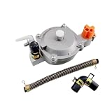
- Compatible with GX160, GX168F, and GX200 engines rated 5.5 to 6.5 horsepower
- Enables conversion to operate on liquefied petroleum gas (LPG) or compressed natural gas (CNG)
- Includes a pressure reducing regulator for consistent gas flow and stable engine function
- Suitable for use in generators, water pumps, and other small engine applications requiring alternative fuel
- construction designed for function in outdoor and industrial environments
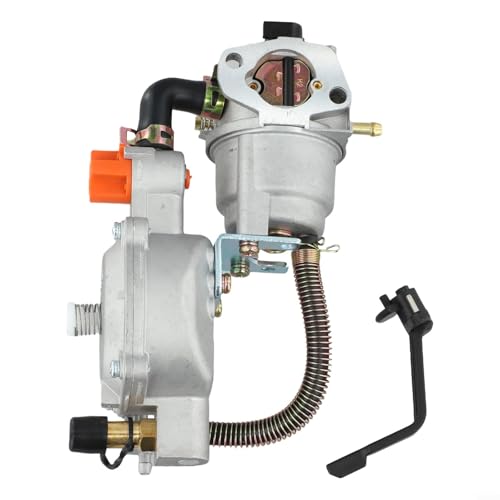
- EASY FUEL CONVERSION: Allows your generator to run on Methane CNG Gas or for LPG Gas with stable performance and no loss of power after installation
- SAFE PRESSURE CONTROL: Built‑in regulator lowers and stabilizes gas pressure before reaching the carburetor for reliable engine start and safe shutdown
- COMPATIBLE FIT: Designed to replace carburetor for 170F for GX160 for GX200 8HP 9HP models, please check dimensions to insure proper fit for your generator
- LONG LASTING BUILD: Robust construction resists wear from low pressure propane or methane gas use, giving consistent performance over time
- QUICK INSTALLATION: Swap your existing carburetor for the included gas carburetor using basic tools, perfect for general backup power setups
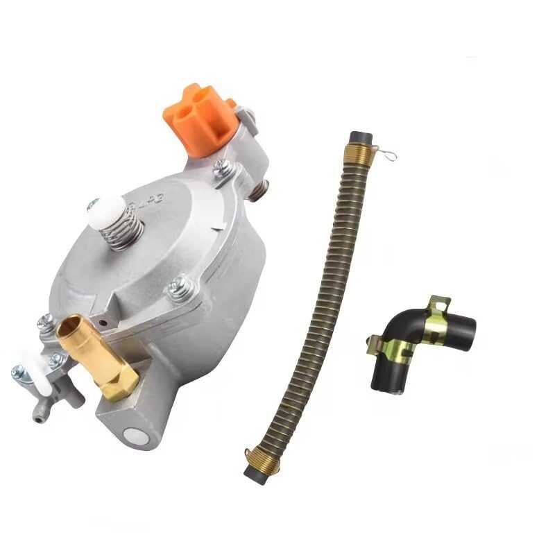
- Material:Metal Color:Silver Weight:500g (Approx.) Quantity: 1set
- Direct Fit for Honda
 GX160/GX168F/GX200 Engines
 - Specifically designed to replace the standard carburetor on 5.5-6.5 HP engines.
- Allowing for precise fine-tuning of fuel flow to ensure stable engine idle and optimal performance.
- Extending engine life, and producing fewer exhaust emissions.
 GX160/GX168F/GX200 Engines
- PRESSURE WASHER ACCESSORY: SIMPSON Dial-N-Wash lets you match pressure output for any cleaning job; Select Max for brick or concrete; Turn to Medium for decks, fences, and wood siding; Choose Min for vehicles, boats, and windows
- EASY TWIST CONTROL: Rotate the dial to Min/Medium/Max to fine-tune pressure; Improve results while reducing risk of damage; Pair with your favorite pressure washer gun, spray wand, and power washer nozzles
- TOOL-FREE SETUP: Attaches between power washer gun and extension wand with industry-standard M22 fittings; Installs in seconds without tools; Works with most gas pressure washer and electric power washer units
- COLD-WATER USE: Rated to 140°F for cold or warm water cleaning; Ideal for everyday residential and commercial tasks; Not designed for soap injection or chemical use
- DURABLE, VERSATILE ACCESSORY: Built for heavy use up to 4500 PSI; Compatible with popular power washer accessories; Great for DIY users and professionals who want control and consistency


- 100% brand-new, never ever been utilized, all parts are tested and quality controlled prior to shipment.
- Manufacturer Part Number:FPS7, 3R3Z-9F972-AA, 3R3Z-9F972-AB, 3R3Z9F972AA, FPS-7; 3R3Z9F972AB, 3R3E-9F972-AA, F8CZ-9F972-BD, F8CZ-9F972-BC; F8CZ-9F972-BE, 3R3E9F972AA, F8CZ9F972BD, F8CZ9F972BC;XW4Z-9F972-BA, XW4Z9F972BA, 3R3Z-9G756-AC, F8CZ9F972BE; 3R3Z9G756AC, F8CF9F972BG, F8CF9F972BE, F8CF9F972BH; F8CF9F972BF, F8CF-9F972-BE, F8CF-9F972-BH;FPS17, FPS-507, F8CF-9F972-BF, F8CF-9F972-BG;PR244, SU10479, SU13804, 5G1142, 5S9017, FPS507, FPS-17.
- Fits For Ford Lincoln Mercury Vehicles with 2.0 2.3 3.0 3.8 3.9 4.6 5.4 Liter V6 V8 L4 Engine : For 2004 2005 Ford Explorer; For 2003 2004 Ford Crown Victoria; For 2004 2005 2006 2007 2008 Ford F150; For 2000 2001 2002 2003 2004 Ford Focus; For 2005 2006 Ford E150 Club Wagon E250 GT; For 2002 2003 2004 2005 2006 2007 Ford Taurus Thunderbird.
- Fits For 1999 2000 2001 2002 2003 2004 Ford Mustang; For 2003 2004 2005 2006 Lincoln Town Car Aviator; For 1998 1999 2000 2001 2002 Lincoln Continental; For 2000 2001 2002 2003 2004 2005 2006 Lincoln LS; For 1998 1999 Mercury Tracer; For 2002 2003 2004 Mercury Sable Marauder Mountaineer Grand Marquis
- Package Include:1x Fuel Pressure Sensor
This product presentation was made with AAWP plugin.