
March 18, 2021 NHTSA CAMPAIGN NUMBER: 21V191000
HV Contactors May Malfunction and Shutdown Battery
An unexpected battery shutdown can cause a loss of motive power, increasing the risk of a crash.
NHTSA Campaign Number: 21V191
Manufacturer Arcimoto Inc
Components ELECTRICAL SYSTEM
Potential Number of Units Affected 181
Summary
Arcimoto Inc (Arcimoto) is recalling certain 2019-2020 FUV, and 2020 Deliverator vehicles. The electronic drivers in some of the high voltage (HV) contactors may malfunction and overheat, which could cause the battery to shutdown.
Remedy
Arcimoto will notify owners, and an Arcimoto factory technician will replace the contactors and related components, free of charge. Arcimoto does not intend to send any dealer or distributor notifications, as it has neither dealers nor distributors at this time. The recall began March 29, 2021. Owners may contact Arcimoto customer service at 1-541-683-6293.
Notes
Owners may also contact the National Highway Traffic Safety Administration Vehicle Safety Hotline at 1-888-327-4236 (TTY 1-800-424-9153), or go to www.safercar.gov.
| Regulatory Recall Report | RRR0023 | ||
| Contactors Excess Resistance May Cause Battery Shutdown | Rev: 0 | ||
| Author: PZ, MM, RS | PO: Dir Regulatory | Appr: Dir Regulatory | Date: 03/09/2021 |
1 SUMMARY
In accordance with Part 573 of Title 49 of the Code of Federal Regulations, Arcimoto Inc. hereby reports a safety issue and intends to recall quantity one-hundred eighty-one (181) Arcimoto Deliverator-1 and FUVs produced between September 19, 2019 and December 31, 2020. Due to an improperly implemented remedy in both Service and Production using the new 003739 B- Return Harness and 004955 Littelfuse, the subject build dates and VIN range was increased. The electronic drivers in some HV contactors may malfunction, causing these contactors to have a higher contact resistance than intended, potentially resulting in overheating. If HV contactors overheat, this can lead to either a blown fuse or opening of the contactors by the BMS, including the traction contactor opening, both of which will lead to unexpected battery shutdown and immediate loss of traction-power, which would make the vehicle more difficult to control and increase the likelihood of a crash.
Note: Fields left blank will be marked “NR” meaning “Not Reported” in public view.
2 NHTSA MANUFACTURER RECALL PORTAL FIELDS
(c)1 IDENTIFICATION OF THE MANUFACTURER, IMPORTER, DISTRIBUTOR, OR BRAND NAME OWNER
| Manufacturer: | Arcimoto, Inc. |
| Address: | 2034 W. 2nd Ave., Eugene OR 97402 |
| Contact: | Gerrit Hurenkamp, Director of Engineering |
(c)2 VEHICLE INFORMATION
| Model Year Start: | Type: |
| 2019 | MOTORCYCLES |
| Model Year End: | Body Style: |
| 2020 | OTHER |
| Make: | Powertrain: |
| Arcimoto | HYBRID ELECTRIC ELECTRIC |
| Model: | Descriptive Information: |
| FUV, Deliverator-1 | Affects all one-hundred eighty-one |
| MY2019 & MY2020 vehicles (fifty-seven
MY2019 T-FUV, one-hundred eighteen MY2020 T-FUV, six MY2020 D-Deliverator-1) produced from 09/19/2019 through to 12/31/2020. |
| Production Dates: | Begin: 09/19/2019 | End: 12/31/2020 |
| VIN Range(s):
(T – FUV, tandem) | Begin:
7F7ATR312KER00000 | End:
7F7ATR317KER00056 |
| VIN Range(s):
(D – Deliverator-1, single) | Begin:
7F7ADR316LER00001 | End:
7F7ADR315LER00006 |
| VIN Range(s):
(T – FUV, tandem) | Begin:
7F7ATR312LER00001 | End:
7F7ATR312LER00094 |
| VIN Range(s):
(T – FUV, tandem) | Begin:
7F7ATR316LER00096 | End:
7F7ATR31XLER00117 |
| VIN Range(s):
(T – FUV, tandem) | Begin:
7F7ATR313LER00119 | End:
7F7ATR31XLER00120 |
(c)3 TOTAL NUMBER POTENTIALLY INVOLVED, (c)4 ESTIMATED PREVALENCE OF DEFECT
| Number potentially involved: 181 | Estimated percentage of involved with defect: 25% |
(c)5 DEFECT / NONCOMPLIANCE DESCRIPTION
For this Defect/Noncompliance:
| Describe the defect or noncompliance: | Describe the safety risk: |
| The electronic drivers in some HV contactors may malfunction, causing these contactors to have a higher contact resistance than intended, potentially resulting in overheating. | If HV contactors overheat, this can lead to either a blown fuse or opening of the contactors by the BMS, including the traction contactor opening, both of which will lead to unexpected battery shutdown and immediate loss of traction-power, which would make the vehicle more difficult to control and increase the likelihood of a crash. |
| If a noncompliance, provide the applicable FMVSS: | Identify any warning which can precede or occur: |
| None. | |
| If applicable, provide any further FMVSS affected: | |
| Describe the cause: | |
| The electronic drivers for the economizer coil in some HV contactors may malfunction, producing out-of-tolerance contact resistance, audible ringing noise, and/or misformed economizer coil current PWM, causing these contactors to have a higher contact resistance than intended, potentially resulting in overheating. | |
| This Recall affects all vehicles. | |
If applicable, identify the manufacturer of the defective or noncompliant component. If the manufacturer of the component is unknown, provide the information for the company that supplied the subject component.
| Component Manufacturer: | |
| Company Information: | Company Contact Information: |
| Company Name: | First Name: |
| [Short version]
Sensata Technologies (formerly Gigavac)
[Long version] Sensata Technologies Inc. (formerly Gigavac) | Derek |
| Country: | Last Name: |
| USA | Turner |
| Address 1: | Position: |
| 529 Pleasant Street | Engineering Manager |
| Address 2: | Email: |
| Mail Station B-49 | [email protected] |
| City: | Phone: |
| Attleboro | Office 805-684-8401 x150
Mobile 508-369-6288 |
| State: | |
| MA | |
| Zip / Postal Code: | |
| 02703 | |
(c)6 CHRONOLOGY OF DEFECT / (c)7 NONCOMPLIANCE DETERMINATION
Provide the chronology of events leading up to the defect decision or test data for the noncompliance decision:
[Short version]
On 5/19/20 a customer reported that while driving their FUV on the hwy, it suddenly coasted to a stop. Arcimoto immediately examined the vehicle, discovered a blown fuse & evidence of overheating involving the contactors. All fuses were immediately tested, but determined to be within acceptable limits & not the Root Cause. Analysis then focused on bus-bars, fasteners, & conductive graphite grease, which were all tested, but they were determined to be within acceptable limits & not the Root Cause. Resistance testing of the contactor closest to the blown fuse was measured to be 1.5 times the acceptable limit. On 7/1 a FUV with reduced speed/acceleration & evidence of overheating involving a contactor measured resistance 1.5 times the acceptable limit. On 7/2, a FUV with reduced speed/acceleration & evidence of overheating involving a contactor measured resistance 3.7 times the acceptable limit.
On 7/3 Arcimoto notified NHTSA of SB-20-003 (20MC8034, 10176916), which sampled vehicles already in the field for evidence of overheating; this method revealed 3 vehicles that each had 1 contactor that exhibited visual evidence of overheating. Upon these findings, vehicle sampling under SB-20-003 was discontinued.
From 7/19 to 10/9, more complex electronic testing on contactors was developed & detected new contactors with excessive contact resistance, audible ringing noise, &/or misformed economizer coil current PWM, each of which could result in overheating. This testing demonstrated the Root Cause of excessive contact resistance within the contactor led to overheating & validated safety concerns about the vehicle population.
Following Arcimoto’s process starting on 5/26 & continuing through 10/12, research data, analysis, & developments were discussed across more than eight meetings. On 11/12, the Engineering & Q&RA Depts presented findings to Arcimoto executives, who decided on 11/17 to validate these findings & notify NHTSA of a Safety Defect.
[Cont’d in Mfr Comments below]
[Long version]
On May 19, 2020 a customer complaint reported that while driving at speed on the highway, an Arcimoto vehicle suddenly coasted to a stop. Arcimoto immediately examined the vehicle, which revealed a blown HV fuse and evidence of overheating involving the HV contactors. All HV fuses were immediately restricted and tested, but consequently determined to be within acceptable limits and not the Root Cause. Analysis was then focused on bus-bars, fasteners, conductive graphite grease, and contactors, which were all restricted and tested, but bus-bars, fasteners, and conductive graphite grease were determined to be within acceptable limits and not the Root Cause. Resistance testing of the contactor closest to the blown fuse was measured to be 1.5 times the acceptable limit. On July 1, 2020 a second Arcimoto vehicle with evidence of overheating involving a HV contactor was identified by visual inspection, was observed thermal-throttling vehicle speed, and similarly measured resistance 1.5 times the acceptable limit. At the same time, a third Arcimoto vehicle with evidence of overheating involving a HV contactor was identified by an overheated battery thermistor closest to the contactor, which had been repeatedly thermal-throttling vehicle speed, and measured resistance 3.7 times the acceptable limit.
Arcimoto immediately notified NHTSA on July 3, 2020 of intent to implement Arcimoto Service Bulletin SB-20-003, recorded by NHTSA as Manufacturing Communication 20MC8034 with NHTSA ID 10176916, which sampled a few customer and company vehicles already in the field and looked for evidence of overheating. On the first thirteen vehicles examined, this method revealed three vehicles that each had at least one HV contactor that exhibited visual evidence of overheating but no functional failures. Upon these findings, vehicle sampling under SB-20-003 was discontinued.
Immediately commencing on July 19 and continuing through October 9, extensive research on contactors with increasingly complex electronic testing was established and maintained, discovering new out-of-the-box contactors with out-of-tolerance contact resistance, audible ringing noise, and/or misformed economizer coil current PWM, each of which could result in overheating. This testing finally demonstrated the Root Cause to lie within the HV contactor, validated safety concerns about excessive contact resistance leading to overheating in the larger vehicle population, and confirmed there is no known advance warning to the vehicle operator of these failures.
Following Arcimoto’s process starting on May 26, 2020 and continuing through October 12, 2020, Engineering and Q&RA Departments performed research and analysis, and internal Stakeholders discussed these latest data and developments across more than eight research meetings. On November 12, 2020, the Engineering and Q&RA Departments presented all documentation and findings to Arcimoto executives, who subsequently decided on November 17, 2020 to validate findings of a Safety issue and to notify NHTSA of a Safety Recall.
For vehicles already remedied under this recall prior to early February 2021, as well as those built after this original defect report but prior to early February 2021, the newly introduced 004955 Littelfuse was later found in some vehicles to be damaged during the installation of 003739B B- Return Harness. Consequently, (i) the subject build dates and VIN range was increased, and (ii) newly introduced parts (003739B B- Return Harness and 004955 Littelfuse) will be rescinded and replaced (with parts 003739C B- Return Harness and 002176 Mersen fuse).
(c)8 IDENTIFY THE REMEDY
Describe the defect/noncompliance remedy program, including the manufacturer’s plan for reimbursement.
Owners will be notified by mail and instructed to contact Arcimoto to schedule a service appointment(s) to have their contactors and related components replaced. There will be no charge to vehicle owners for this service. To the best of our knowledge, no owners have incurred any costs resulting from this defect.
Describe what distinguishes the remedy component from the recalled component.
Using Arcimoto’s new advanced electronic testing, all HV contactors in customers’ vehicles will be extensively inspected and tested, and any identified as out-of-tolerance will be replaced with contactors tested to be within acceptable limits.
All HV electronics inside the compartment for the traction-power battery will be replaced with redesigned sub-assemblies, including (i) the bus-bars attached to the contactors have been enlarged for increased radiative capacity, (ii) a heat-sink has been added to a rear bus-bar, and (iii) a redundant second fuse for the traction-power battery has been eliminated.
Additionally, due to an improperly implemented remedy in both Service and Production, the subject build dates and VIN range was increased to reflect these additional vehicles. Specifically, for vehicles built after this original defect report as well as those remedied under this recall prior to early February 2021, newly introduced parts (003739B B- Return Harness and 004955 Littelfuse) will be rescinded and replaced (with parts 003739C B-
Return Harness and 002176 Mersen fuse).
Identify and describe how and when the recall condition was corrected in production.
Using Arcimoto’s new advanced electronic testing, all HV contactors received from Component Manufacturer will be extensively inspected and tested, to ensure all product is within acceptable limits.
For vehicles in-process or already produced prior to November 18, 2020 :
All HV contactors already in vehicles will be re-tested, and any identified as out-of-tolerance will be replaced with contactors tested to be within acceptable limits. All HV electronics inside the compartment for the traction-power battery will be reworked with redesigned sub-assemblies, including (i) the bus-bars attached to the contactors have been enlarged for increased radiative capacity, (ii) a heat-sink has been added to a rear bus-bar, (iii) a redundant second fuse has been eliminated, and (iv) only for vehicles already remedied under this recall prior to early February 2021, newly introduced harness and fuse will be rescinded and replaced with originally-designed harness and fuse.
For vehicles produced on or after November 18, 2020 :
All HV electronics inside the compartment for the traction-power battery will have redesigned sub-assemblies, including (i) the bus-bars attached to the contactors have been enlarged for increased radiative capacity, (ii) a heat-sink has been added to a rear bus-bar, (iii) a redundant second fuse has been eliminated, (iv) only for vehicles built after this original defect report but prior to early February 2021, newly introduced harness and fuse will be rescinded and replaced with originally-designed harness and fuse, and (v) the rear access-hole of the compartment for the traction-power battery has been enlarged.
| Describe the recall schedule for notifications: | Planned Dealer Notification Begin Date: |
| Arcimoto does not intend to send any dealer or distributor notifications, as it has neither dealers nor distributors at this time. | N/A |
| Planned Dealer Notification End Date: | |
| N/A | |
| Planned Owner Notification Begin Date: | |
| 03/22/2021 |
IDENTIFY THE RECALL SCHEDULE
| Planned Owner Notification End Date: | |
| 04/09/2021 | |
| Manufacturer’s identification code for this recall (if applicable): |
Please be reminded that owner notification letters must be mailed no more than 60 days from submission of this report.
MANUFACTURER COMMENTS TO NHTSA STAFF
Arcimoto does not intend to send any dealer or distributor notifications, as it has neither dealers nor distributors at this time.
[Continuation of Chronology of Events:]
For vehicles already remedied under this recall prior to early February 2021, as well as those built after this original defect report but prior to early February 2021, the newly introduced 004955 Littelfuse was later found in some vehicles to be damaged during the installation of 003739B B- Return Harness. Consequently, (i) the subject build dates and VIN range was increased, and (ii) newly introduced parts (003739B B- Return Harness and 004955 Littelfuse) will be rescinded and replaced (with parts 003739C B- Return Harness and 002176 Mersen fuse).
DOCUMENT UPLOAD
1.1 (c)10 A representative copy of all notices, bulletins, and other communications that relate directly to the defect or noncompliance and are sent to more than one manufacturer, distributor, dealer or purchaser. These copies shall be submitted to NHTSA’s Recall Management Division (NVS-215)
3 REVISION HISTORY
| Function | Role | Name | Signature | Date |
| Author | Dir Regulatory | Pete Z | <insert name> | 03/09/2021 |
| Author | RA-RCP | Matt M | <insert name> | 03/09/2021 |
| Author | RA-RCA | Raymond S | <insert name> | 03/09/2021 |
| Author | Dir Engineering | Gerrit H | <insert name> | 03/09/2021 |
| PO | Dir Regulatory | Pete Z | <insert name> | 03/09/2021 |
| Approver | Dir Regulatory | Pete Z | <insert name> | 03/09/2021 |
| Revision | Reason for change;
Summary of change from prior Revision | |
| # | Date Issued | |
| 0 | 11/18/2020 | Initial Issue
Internal Outline of Defect and Noncompliance Report Format pursuant to §573.6. (Incorrect online portal submission resulted in original submission & Amendment 1 submission using this same R0.) |
| 1 | 11/19/2020 | Clarification
Added details. Equivalent to Amendment 2. |
| 2 | 03/09/2021 | Corrections
Changed remedy descriptions per to-date PCM meeting agreements & ECO-401. Equivalent for new recall campaign. |
| Regulatory Recall Remedy Method-Sheet | RRM0015 | ||
| 21V191 Contactors Excess Resistance May Cause Battery Shutdown | Rev: 0 | ||
| Author: LC,MM,PZ | PO: Dir GRC | Appr: Dir GRC | Date: 04/12/2021 |
1 PURPOSE
Safety Recall Remedy Instructions: Contactors
2 AFFECTED VEHICLES
| Model Year | Model | VIN Range (last 8 digits) |
| 2019 | FUV Evergreen | KER00000 – KER00056 |
| 2020 | FUV Evergreen | LER00001 – LER00007 |
| 2020 | FUV Evergreen | LER00009 – LER00091 |
| 2020 | FUV Evergreen | LER00096 – LER00096 |
3 BACKGROUND
The electronic drivers in some HV contactors may malfunction, causing these contactors to have a higher contact resistance than intended, potentially resulting in overheating. If HV contactors overheat, this can lead to either a blown fuse or opening of the contactors by the BMS, including the traction contactor opening, both of which will lead to unexpected battery shutdown and immediate loss of traction-power, which would make the vehicle more difficult to control and increase the likelihood of a crash.
4 OWNER NOTIFICATION
Owners of affected vehicles will be sent a notification of this campaign.
5 CORRECTIVE ACTION
A trained Arcimoto Service Technician will remedy the defective parts by replacing the HV contactors.
6 PARTS INFORMATION
Panel – Left Lower Dash (002982)
Panel – Right Lower Dash (002983)
Handlebar Assy (002109)
Panel – Left Dash Collar (002970)
Panel – Right Dash Collar (002971)
Display Assy (004612)
Dash Center Panel Assy (004975)
Seat Base (004140)
Seat Back (004141)
Cargo Box Assy (003158)
Rear Left Side Panel (002998)
Rear Right Side Panel (002999)
Rear Center Panel Assy (003000)
Rear Wheel Liner Panel (003001)
Chassis Lid (003144)
Backbone Assembly (003105)
B-Return Harness (003739)
Battery Electronics Assy (003524)
Harness – BMS (002309)
Busbar – Mid-Pack (003024)
Battery Bay Assy (003196)
Battery Electronics Assy V2 (004947)
Busbar – Contactor to Battery (004910)
Backbone Assembly (003105)
Rear Large Access Plate (004906)
Busbar – Contactor to Battery (004910)
B-Return Harness V2 (004956)
Busbar Heatsink (004950)
FUSE, 400A, 300V (004955)
Note : The first ten vehicles serviced for this recall will use (new) Battery Electronics Assy V2 ( 004947 ) parts. After that, all vehicles serviced for this recall will use (refurbished) “004947-R” Battery Electronics Assy V2 parts.
7 RELATED DOCUMENTS AND RESOURCES
- Battery Electronics Assy V2 (004947)
- Backbone Assembly (003105)
8 SAFETY REQUIREMENTS
8.1 Required Training
Arc-Flash Safety Training
8.2 Required Protective Gear
Full PPE, category 2, 8 Cal/cm2 (Suit, Gloves and Helmet) for use by the technician working directly on the vehicle
6-foot non-conductive pole or rod, for use by Spotter if necessary
9 SERVICE PROCEDURE
9.1 Remove the Left Lower Dash Panel ( 002982) and the Right Lower Dash Panel (002983).
9.2 Remove HV Power From the FUV:
9.2.1 Press the red button on the 12V Circuit Breaker to flip the yellow RESET lever down to the OFF The 12V Circuit Breaker is accessed via the right-side access port.
9.2.2 On each of the (RED and YELLOW) Power Output Connectors, press the locking tab down, and gently pull to unplug the Power Output The Power Output Connectors are accessed via the left-side service port.
9.3 Remove the Handlebar Assy (002109).
9.4 Remove the Left Dash Collar Panel ( 002970 ) and the Right Dash Collar Panel (002971).
9.5 Remove the Display Assy (004612).
9.6 Remove the Center Dash Panel Assy ( 004975 ).
9.7 Remove the Front and Rear Seat Bases ( 004140 ).
9.8 Remove the Front Seat Back (004141).
9.9 Remove the Cargo Box Assy ( 003158 ), if equipped.
9.10 Remove the Rear Left Side Panel (002998 ) and the Rear Right Side Panel ( 002999 ).
9.11 Remove the Rear Center Panel Assy (003000).
9.12 Remove the Rear Wheel Liner Panel ( 003001 ).
9.13 Safely elevate the front of the vehicle and set on jack stands.
9.14 Disconnect the three connectors on top of the Battery Electronics Assy (003524):
9.14.1 Disconnect the orange 2-pin connector (HV Accessory Bulkhead Connector Harness ( 003361 )).
9.14.2 Disconnect the blue 18-pin connector (Backbone Harness ( 003343 )).
9.14.3 Disconnect the two-position Powerlok 300 Connector Assy (003360 ).
9.15 Remove the 22 hex flange bolts (M6-1.0 X 12) that secure the Chassis Lid to the Backbone Do not remove the Chassis Lid until Arc-Protection is deployed (see 16).
9.16 Remove the eight socket head cap screws (SHCS, M5-0.8 X 10 ZN) and washers (M5) that secure the BatteryElectronics Assy to the Chassis Lid.
9.17 At this the technician working on the vehicle must put on full Arc-Protection gear (PPE, category 2, 8Cal/cm2 Suit, Gloves and Helmet) before proceeding.
9.18 Position the Spotter, equipped with a 6- foot non-conductive pole or rod, approximately six feet away from the The Spotter must be positioned such that they can clearly observe the technician and intervene in case of an emergency before proceeding.
9.19 Remove the Chassis Lid ( 003144 ).
9.20 Remove the two 4-40 X 1/8″ security screws, then disconnect the BMS Connector on the Front Battery
9.21 Remove the two 4-40 X 1/8″ security screws, then disconnect the BMS Connector on the Rear Battery
9.22 Remove the Mid-Pack Busbar ( 003024 ) which connects the Front and Rear Battery Modules (located in the center of the Battery Bay):
9.22.1 Remove the black plastic safety cap from the rear (-) terminal on the Front Battery Module.
9.22.2 Remove the red plastic safety cap from the front (+) terminal on the Rear Battery Module.
9.22.3 Remove the eight socket head cap screws (SHCS, M4-0.7 X 16) and washers (4.3 ID/ 9 OD / 0 thick, BellevilleSpring), that secure the Mid-Pack Busbar ( 003024 ) to the Front and Rear Battery Modules, and remove the Mid-Pack Busbar.
9.22.4 Replace the Safety Caps.
9.23 Disconnect the BMS Harness ( 002309 ) from the Battery Electronics
9.24 Remove the BMS Harness and set it aside.
9.25 Disconnect the Mid-Pack Busbar ( 003024 ) that connects the Front Battery Module to the Battery Electronics Assy:
9.25.1 Remove the red plastic safety cap from the front (+) terminal on the Front Battery Module.
9.25.2 Remove the four socket head cap screws (SHCS, M4-0.7 X 16) and washers (4.3 ID/ 9
OD / 1.0 thick, BellevilleSpring) that secure the Mid-Pack Busbar ( 003024 ) to the positive terminal on the Front Battery Module.
9.25.3 Replace the Safety Cap.
9.26 Unclip the four cable ties that secure the B-Return Harness to the Front and Rear Battery Modules.
9.27 Disconnect the B-Return Harness ( 003739 ) from the Battery Electronics Assy:
9.27.1 Remove the four screws (SHCS, M4-0.7 X 16) and washers (4.3 ID/ 9 OD / 1.0 thick, Belleville Spring) that secure the B-Cable to Battery Electronics Busbar ( 003787 ) to the front-end terminal on the B-Return Harness.
9.27.2 Move the B-Return Harness away from the Battery Electronics Assy.
9.28 Remove the FCG Connector on the Backbone Harness ( 003343 ) from the Quick Connect Tab on the front left of the Battery Bay.
9.29 Pull the Backbone Harness and the BMS Harness up and out of the Battery Bay, to provide slack to allow removal of the Battery Electronics Assy.
9.30 From beneath the vehicle, remove the six hex flange bolts (M6-1.0 X 12) that secure the Battery Electronics Assy (0 03524 ) to the Battery Bay Assy (0 03196 ).
9.31 Gently lift the Battery Electronics Assy out of the Battery Bay Assy, taking care not to damage the wiring and connectors.
9.32 Remove the Backbone Harness (0 03343 ) from the Battery Electronics Assy:
9.32.1 Slide the red plastic Slide-Clip off of the blue BFJ connector.
9.32.2 Push the blue BFJ connector through the connection plate, and remove the Backbone Harness.
9.32.3 Move the Backbone Harness BFJ out of the way, but leave it installed in the Battery Bay because it will be used in the new Battery Electronics Assy V2 (see step 9.35).
9.33 Disconnect all connectors from the Battery Electronics Assy, and set the Battery Electronics Assy aside.
9.34 Remove the Backbone Harness from the (new) Battery Electronics Assy V2 ( 004947 ):
9.34.1 Slide the red plastic Slide-Clip off of the blue BFJ connector.
9.34.2 Push the blue BFJ connector down and through the connection plate, and remove the Backbone Harness.
9.35 Install the Backbone Harness that was removed from the original Battery Electronics Assy (see step 28) into the new Battery Electronics Assy V2:
9.35.1 Insert the blue BFJ connector on the Backbone Harness from underneath the connection plate on the Battery Electronics Assy V2.
9.35.2 Slide the red plastic Slide-Clip onto the BFJ connector to secure it to the connection plate.
9.36 Install a new Battery Electronics Assy V2 ( 004947 ):
Note: The first ten vehicles serviced for this recall will use (new) Battery Electronics Assy V2 ( 004947 ) parts. After that, all vehicles serviced for this recall will use (refurbished) “004947-R” Battery Electronics Assy V2 parts.
9.36.1 Reconnect all connectors to the Battery Electronics Assy V2.
9.36.2 Insert the Battery Electronics Assy V2 into position at the front of the Battery Bay Assy. Ensure that the straight horizontal Busbar ( 003024 ) extending from the Battery Electronics Assy V2 is properly aligned with the front (+) terminal on the Front Battery
Module.
9.36.3 Use six hex flange bolts (M6-1.0 X 12) to secure the Battery Electronics Assy V2 to the Battery Bay Assy. Use new fasteners and torque all bolts to 8 FT-LBS, and apply torque seal.
9.36.4 Attach the Contactor to Battery Busbar ( 004910 ) to the front (+) terminal on the Front Battery Module. Use new fasteners (four screws (SHCS, M4-0.7 X 16) and washers (4.3 ID/ 9 OD / 1.0 thick, Belleville Spring). Torque all screws to 25 IN-LBS, and apply torque seal.
9.37 Remove the busbar that connects the Rear Battery Module to the Rear (Negative Terminal) Contactor Assy (0 03742 ):
Note: This busbar is an assembly of three component busbars ( 003729 , 003730 and 003024 ). Leave this busbar assembly intact, and remove it as one piece.
9.37.1 Remove the black plastic safety cap from the rear (-) terminal on the Rear Battery Module.
9.37.2 Remove the four socket head cap screws (SHCS, M4-0.7 X 16) and washers (4.3 ID/ 9 OD / 1.0 thick, Belleville Spring) that secure the busbar to the negative terminal on the Rear Battery Module.
9.37.3 Remove the bolt that secures the busbar to the Rear Contactor Assy.
9.37.4 Remove the busbar and set aside.
9.38 Remove the B-Return Harness ( 003739 ):
9.38.1 Remove the bolt that secures the B-Return Harness to the Rear Contactor Assy.
9.38.2 Pull the B-Return Harness (with Busbar – Rear Contactor to Fuse (003731) and 400A Fuse (0 04955 ) attached) out of the Battery Bay, and set aside.
9.39 Remove the Rear (Negative Terminal) Contactor Assy (0 03742 ):
9.39.1 Remove both socket head cap screws (SHCS, M5-0.8 X 20) that secure the Rear Contactor Assy to the Battery Bay.
9.39.2 Pull the Rear Contactor Assy out of the Battery Bay and set aside.
9.40 Install the new B-Return Harness V2 ( 004956 ), pre-assembled with Heatsink Busbar ( 004950 ) and 400A Fuse (0 04955 ):
Note: Before installing the new B-Return Harness V2 ( 004956 ), visually check the crimp orientation of the rear 5/16” cable-lug terminal. Ensure that the crimp orientation of the rear cable-lug terminal is perpendicular (not parallel) to the surface of the cable-lug terminal.
If the crimp orientation on the new B-Return Harness V2 ( 004956 ) is incorrect, the cable must be refurbished before it can be used.
9.40.1 Route the front end of the B-Return Harness V2 through the Access Port at the rear of the Backbone Assy, to the Battery Electronics Assy V2 (at the front)
9.40.2 Attach the front connector of the B-Return Harness V2 to the B-Cable to Battery Electronics Busbar ( 003787 ) extending from the Battery Electronics Assy V2. Use new fasteners (four socket head cap screws (SHCS, M4-0.7 X16) and washers (4.3 ID/ 9 OD / 1.0 thick, Belleville Spring). Torque all screws to 25 IN-LBS, and apply torque seal.
9.40.3 Install four Cable Ties ( 002259 ) at the four Cable Tie Mounts ( 003757 ) to secure the B-Return Harness to the Front and Rear Battery Modules.
9.41 Install the new Rear (Negative Terminal) Contactor Assy (0 03742 ):
9.41.1 Insert the new Rear Contactor Assy into position through the Access Port at the rear of the Backbone Assy. The raised notch on the top surface of the Contactor should face to the rear.
9.41.2 Use two socket head cap screws (SHCS, M5-0.8 X 20) to secure the new Rear Contactor Assy to the Battery Bay.
Use new fasteners and torque both screws to 25-30 IN-LBS, and apply torque seal.
9.42 Install the busbar that connects the Rear Contactor Assy to the Rear Battery Module:
9.42.1 Attach the top of the busbar to the negative terminal on the Rear Battery Module. Use new fasteners (four screws (SHCS, M4-0.7 X 16) and washers (4.3 ID/ 9 OD / 1.0 thick, Belleville Spring). Torque all screws to 25 IN-LBS, and apply torque seal.
9.42.2 Use the nut supplied with the contactor, and washer (8.4 ID/ 18 OD / 2.0 thick, Belleville Spring) to secure the bottom of the busbar to the left-side post on the Rear Contactor Assy. Torque nut to 7.5 FT-LBS, and apply torque seal.
9.42.3 Replace the black plastic safety cap on the rear (-) terminal on the Rear Battery Module.
9.43 Attach the Heatsink Busbar (attached to the B-Return Harness V2 ( 004956 )) to the Rear Contactor Assy:
9.43.1 Position the Heatsink so that the fins face to the front.
9.43.2 Use the nut supplied with the contactor, and washer (8.4 ID/ 18 OD / 2.0 thick, Belleville Spring) to secure the bottom of the busbar to the right-side post on the Rear Contactor Assy. Torque nut to 7.5 FT-LBS, and apply torque seal.
9.44 Replace the Rear Large Access Plate (004906), and secure it with silicone bead and four hex flange bolts (M6-1.0 X12). Torque bolts to 8 FT-LBS, and then apply torque seal.
9.45 Tuck the harnesses in the Battery Bay between the left side of the Battery Modules and the wall of the Battery Bay.
9.46 Re-install the Mid-Pack Busbar (003024). Use new fasteners (four socket head cap screws (SHCS, M4-0.7 X 16) and washers (4.3 ID/ 9 OD / 1.0 thick, Belleville Spring). Torque all screws to 25 IN-LBS, and apply torque seal.
9.47 Re-connect the BMS Harness (002309) in the following order:
9.47.1 First, connect the BMS Connector on the Rear Battery Module, and secure the connector with two 4-40 X 1/8″security screws.
9.47.2 Next, connect the BMS Connector on the Front Battery Module, and secure the connector with two 4-40 X 1/8″security screws.
9.47.3 Re-connect the front end connectors in the Battery Electronics Assy.
9.48 Reinstall the Chassis Lid (003144) on the Backbone Assy (003105). Use 22 hex flange bolts (M6-1.0 X 12). Torque all bolts to 8 FT-LBS, and apply torque seal.
9.49 Reinstall the Rear Wheel Liner Panel (003001).
9.50 Reinstall the Rear Center Panel Assy (003000).
9.51 Reinstall the Rear Left Side Panel (002998) and the Rear Right Side Panel (002999).
9.52 Reinstall the Cargo Box Assy (003158), if equipped.
9.53 Reinstall the Front Seat Back (004141).
9.54 Reinstall the Front and Rear Seat Bases (004140).
9.55 Reinstall the Center Dash Panel Assy (004975).
9.56 Reinstall the Display Assy (004612).
9.57 Reinstall the Left Dash Collar Panel (002970) and the Right Dash Collar Panel (002971).
9.58 Reinstall the Handlebar Assy (002109).
9.59 Restore HV power to the FUV:
9.60 Reinstall the Left Lower Dash Panel (002982) and the Right Lower Dash Panel (002983).
9.61 Safely lower the FUV.
10 REVISION HISTORY
| Function | Role | Name | Signature | Date |
| Author | Tech’l Content Writer | Larry C | <insert name> | 04/12/2021 |
| Author | GRC Paralegal | Matt M | <insert name> | 04/12/2021 |
| Author | Dir GRC | Pete Z | <insert name> | 04/12/2021 |
| PO | Dir GRC | Pete Z | <insert name> | 04/12/2021 |
| Approver | Dir GRC | Pete Z | <insert name> | 04/12/2021 |
| Checker | RCP | Matt M | <insert name> | 04/12/2021 |
| Revision | Reason for change;
Summary of change from prior Revision | |
| # | Date Issued | |
| 0 | 04/12/2021 | Initial Issue
Safety Recall Remedy Instructions: Contactors NHTSA recall ID has changed from 20V717 to 21V191 |
3 Affected Products
Vehicles
| MAKE | MODEL | YEAR |
| ARCIMOTO | DELIVERATOR | 2020 |
| ARCIMOTO | FUV | 2019-2020 |
11 Associated Documents
Part 577 Owner Notification Envelope
Recall Acknowledgement
RCAK-21V191-6996.pdf 645.578KB
Miscellaneous Document – Regulatory Recall Report re Contactors Excess Resistance May Cause Battery Shutdown
RMISC-21V191-1087.pdf 282.385KB
Recall 573 Report
RCLRPT-21V191-3728.PDF 216.676KB
Defect Notice 573 Report
RCLRPT-21V191-7001.PDF 216.676KB
Recall 573 Report
RCLRPT-21V191-1101.PDF 219.349KB
Remedy Instructions and TSB
RCRIT-21V191-5019.pdf 314.733KB
Recall Quarterly Report #2, 2021-2
RCLQRT-21V191-1387.PDF 211.232KB
Recall Quarterly Report #1, 2021-1
RCLQRT-21V191-4306.PDF 211.128KB
Recall Quarterly Report #4, 2021-4
RCLQRT-21V191-1581.PDF 211.419KB
Recall Quarterly Report #3, 2021-3
RCLQRT-21V191-6410.PDF 211.315KB
Latest Recalls Documents

- Flex Level 1 EV Charger - The EVDANCE Level 1 electric car charger is compatible with J1772 electric vehicles and plug-in hybrid vehicles (North American Standard). *Tesla requires a SAE J1772 adapter.
- Convenient to Use - This charger has both NEMA 6-20 plug for 16A 240V charging (3.68kW, 10-12 mi/h) and a NEMA 6-20 to 5-15 plug adapter for 12A 120V charging (1.44kW, 2-5 mi/h). The included bag makes it easier to carry on the go. It also has a 25ft cable length, you can use it flexibly from anywhere in the garage or driveway.
- Check Your Outlet Type -This charger works with standard 120V NEMA 5-15/5-20 outlets (2-5 mph charging speed) and 240V NEMA 6-20 outlets (10-12 mph) . It's not compatible with NEMA 6-15/10-30/14-30/14-50/6-50 outlets – you'll need a NEMA 14-50/14-30/10-30/6-50 to 6-20 adapter (sold separately) to connect.
- Compatible EV Models -This EV charger works with most major electric vehicles, including Ford, Chevrolet, Hyundai, Audi, Nissan Ariya, Rivian R1S, Kia, and others. However, it's not compatible with Mini Cooper Electric Hardtop,Toyota Prus Prime/Z4X/RAV4Prime, Porsche Taycan Base/4S/Turbo/Turbo S or Tesla models (Tesla requires a J1772 to Tesla Adapter, sold separately). For a full list of compatible models, check out the Full Compatibility List on our product page.
- Indication Displays - LED display that can tell you the status as well as indicate errors while charging your electric vehicle.

- WORKS WITH EVERY NON-TESLA EV: Standard J1772 connector plugs straight into Ford, Chevrolet, Hyundai, Kia, Nissan, BMW, Volkswagen, Audi, Rivian, Lucid and every other EV or plug-in hybrid sold with a J1772 port - no adapter needed. Tesla drivers can charge too, using the J1772 adapter that comes with the car.
- PLUG IN, NO HARDWIRING: Level 2 charger delivers up to 40A to fully charge most EVs overnight. Plugs into a 240V, 4-prong NEMA 14-50 outlet (the RV/range type - NOT a dryer outlet) on a dedicated 50A circuit. The extra-long 25 ft cable easily reaches across a garage or driveway. Before ordering, check your car's port type and that you have the right outlet.
- CONTROL & SAVE FROM YOUR PHONE: A stronger built-in antenna keeps the charger online even in a garage or basement. Use the free app to start/stop charging, set speed (6-40A), get reminders, and track energy use and cost. Schedule off-peak overnight charging to cut your electric bill. Requires 2.4 GHz WiFi.
- SAFETY-CERTIFIED & WEATHERPROOF: Independently tested and certified (UL, ETL, FCC, Energy Star). A fully sealed IP66 / NEMA 4 housing stands up to rain, snow, heat and dust indoors or out, and internal steel shielding protects the electronics for years of reliable use.
- GLOW-IN-THE-DARK HOLSTER: The included high-visibility holster glows in the dark so you can find and dock the plug easily at night. Holds the connector securely when not in use.
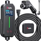
- [2026 INTELLIGENT CHARGING UPGRADE — PRECISION CONTROL MEETS SMART SCHEDULING] After surveying 100K+ U.S. EV owners, the Raylix R&D team found that nearly all drivers recognized the necessity of adjustable current and scheduled charging. Our upgraded J1772 charger features 4-level adjustable current (8A/10A/12A/16A) and a 1–12 hour smart delay timer. Whether you're charging overnight or during off-peak hours, enjoy smarter energy use, lower costs, and total convenience—on your schedule.
- [ONE CHARGER, ALL J1772 EVs/PHEVs READY!] Compatible with all SAE J1772 electric vehicles and plug-in hybrids—whether it’s Ford, GM, Nissan, Audi, BMW, Kia, Hyundai, Honda, Chevy, or more. Perfect for home or on-the-road charging, our 16A Level 1 & 2 charger ensures your EV is always powered and ready for any journey.
- [CHARGE 4× FASTER — NO MORE WAITING] In a rush? Our 16A Level 1 & 2 charger delivers charging speeds up to 4× faster than standard 8A Charger Level 1. Whether it's an early commute, a spontaneous trip, or last-minute errands, your EV will be ready when you are.
- [LEVEL 1 & 2 PORTABLE CHARGER — CHARGE ANYWHERE, ANYTIME] Designed for maximum flexibility, Raylix Level 1 & 2 EV charger features both 5-15 and 6-20 plug compatibility. Whether you're charging in your garage, at a friend's house, or at a roadside motel. NEMA 6-20 plug for Level 2 ev charging (240V, 16A, 3.68kW, 9-12 miles/hr) and a NEMA 5-15 adapter for Level 1 ev charging (120V, 12A, 1.44kW, 3-5 miles/hr) NOTE: In compliance with North American electrical safety standards, the charger automatically limits current to 12A when using a 5-15 outlet—protecting both your vehicle and your home’s electrical system.
- [AT-A-GLANCE CHARGING COMMAND: TOTAL CONTROL, INSTANTLY] While most ev chargers solutions confine vital data to in-car screens, the Raylix tesla charger breaks free with its enhanced TFT color display. This Raylix-exclusive feature delivers crystal-clear, real-time updates—voltage, current, power load, AND critical charging temperature—directly on the unit. Just one glance gives you complete charging insight. It’s not just information; it's the empowering peace of mind and satisfying control that transforms every charge into a masterfully managed experience.

- [Up to 9x Faster Charging Speed]: Provides up to 46 miles/hour charging speed via hardwired connection (48 amp - up to 9x faster than a standard wall outlet) or up to 38 miles/hour via the NEMA 14-50 plug (40 amp). Professional installation recommended for optimal safety and performance. [Install The Power Outlet Cord]: No smaller than 8AWG if charge 40-48A, we suggest 6AWG cord.(1.The input side is belongs to the electrician electric automobile regulation scope, need to use three 6AWG cable wires for 48A; 2.The charging cable belongs to the automotive connector certification standard, so the 8AWG cable can meet the 48A.)
- [DESIGNED WITH J1772 Connector for All North America j1772 Connector EVs/PHEVs. Not fits for Tesla/Nacs Connector Cars(j1772 to Tesla adapter needed)]: Compatible with Tesla cars (Adapter needed, not included), Ford, GM, Audi, Kia, Honda, Kia, Hyundai, Gmc, Chevrolet Bolt, VW ID 4, Nissan Leaf, Ford Mustang Mach-E, IONIQ 5 2024 and before, BMW i3, i4, iX, Jeep Wrangler 4xe, etc. [Not fits for Nac connector cars-Kia EV6 2025/EV9,Ariya 2025&2025 loniq 5(J1772 to Tesla adapter needed)]
- [Safety & Faster Charging with ETL, FCC, Energy Star Certified]: Meets the Safety Criteria Defined by: SAE J1772, UL2231-1/-2, UL 991, UL 2231, UL 2251, UL1998 and UL 2594. (ETL and FCC certified EV car charger with 3-year Warranty)
- [Plug-play Mode(The Default Setting), Smart Touch Screen, No APP Needed]: Clearly show the charging amperage, charging speed, input voltage, delay time, etc. For the touch buttons: 1. Pull out the charging gun before press the buttons, otherwise no respond; 2. Long press "Ⓐ" or "Time" button to enter the setting interface, then you can adjust the amperage from 16A to 48A freely or Set the charging start time; 3. You can do "factory reset" if doesn't charging.
- [Smart WIFI APP, You can Set the Charging Period]: By APP, you can wirelessly check the charging cost, history, fully-charged notification, track the charging status, during off-peak period, etc. [Wi-Fi Reset/Factory Reset Function, Add New Device Quickly]: If you can't find your device or you have replaced a new phone, just pull out the charging latches, simultaneously long press the Ⓐ button and time adjustment button on the product screen until it shows "Factory Reset", then wait 3-5 seconds and re-start your device.


- WORKS WITH EVERY NON-TESLA EV: Standard J1772 connector plugs straight into Ford, Chevrolet, Hyundai, Kia, Nissan, BMW, Volkswagen, Audi, Rivian, Lucid and every other EV or plug-in hybrid sold with a J1772 port - no adapter needed. Tesla drivers can charge too, using the J1772 adapter that comes with the car. The extra-long 25 ft cable easily reaches across a garage or driveway.
- HARDWIRED - PROFESSIONAL INSTALL: This Level 2 charger is hardwired (not plug-in), so a licensed electrician installs it per National Electrical Code. It delivers up to 48A on a dedicated 60A, 240V circuit - enough to charge most EVs fully overnight. Want more speed? You can set DIP switches 4 and 5 to unlock 50A on a dedicated 70A circuit. Before ordering, check your car's port type and that your electrical panel can support the circuit.
- CONTROL FROM YOUR PHONE: A stronger built-in antenna keeps the charger online even in a garage or basement. Use the free app to start and stop charging, set the charging speed (6-48A), get reminders, and track how much energy and money each charge uses. Requires a 2.4 GHz home WiFi network.
- SAFETY-CERTIFIED & WEATHERPROOF: Independently tested and certified (UL, ETL, FCC, Energy Star). A fully sealed IP66 / NEMA 4 housing stands up to rain, snow, heat and dust indoors or out, and internal steel shielding protects the electronics for years of reliable use.
- GLOW-IN-THE-DARK HOLSTER: The included high-visibility holster glows in the dark so you can find and dock the plug easily at night. Holds the connector securely when not in use.
This product presentation was made with AAWP plugin.