
March 15, 2018 NHTSA CAMPAIGN NUMBER: 18V178000
Valve Train Adjustment Screw may Fall Off
The damage to the engine may result in it shutting off and increasing the risk of a crash.
NHTSA Campaign Number: 18V178
Manufacturer Hino Motors Sales U.S.A., Inc.
Components ENGINE AND ENGINE COOLING
Potential Number of Units Affected 45
Summary
Hino Motor Sales U.S.A., Inc. (Hino) is recalling certain 2018-2019 NE8J, NJ8J, and NV8J trucks. The engine valve train adjustment screw lock nuts may not have been properly tightened manufacturing, possibly resulting in them coming loose within the engine and damaging it.
Remedy
Hino will notify owners, and dealers will inspect the torque on the valve train adjustment screw lock nuts. If a nut is found missing, the engine will be replaced, free of charge. The recall began on May 18, 2018. Owners may contact Hino customer service at 1-248-699-9390. Hino’s number for this recall is AA9Q0.
Notes
Owners may also contact the National Highway Traffic Safety Administration Vehicle Safety Hotline at 1-888-327-4236 (TTY 1-800-424-9153), or go to www.safercar.gov.
SAFETY RECALL
AA9Q0 CONVENTIONAL VALVETRAIN
ADJUSTMENT SCREW LOCK NUT
INSPECTION/REPAIR
RECALL NO: AA9Q0
DATE: 3-15-2018
REFERENCE: QA-180314-N1
SUBJECT VEHICLES:
18MY-19MY Conventional Trucks equipped with a J08 engine
OVERVIEW:
The programming of the automatic tightening equipment used to tighten valve train adjustment screw lock nuts in the engines of the subject vehicles was improper. As a result, the following procedure provides directions for the inspection and repair of the adjustment screw lock nuts.
NEW VEHICLES IN DEALERSHIP INVENTORY
As required by Federal law (49 Code of Federal Regulations §577.13), dealerships are not to deliver any new vehicles in their inventory that are involved in a Safety Recall unless the vehicle has been remedied. Refer to the appropriate Vehicle Identification Number (VIN) list to determine vehicle eligibility.
Note: Refer to the appropriate Vehicle Identification Number in the warranty system to determine vehicle eligibility.
BEFORE YOU BEGIN:
- Read and understand all instructions and procedures before you begin the work.
- Read and follow all WARNINGS and NOTICES set forth in this publication. These alerts help to avoid damage to components, serious personal injury, or both.
- Park the vehicle on a flat, level and solid surface and apply the parking brake.
- Place the gear shift lever in “Neutral” or “N”.
- Confirm the engine is stopped, the starter switch is in the off (LOCK) position, and the key is removed.
- Always wear safety glasses to prevent eye injuries.
- Place wheel chocks in front of and behind all the wheels.
- Engine temperature has cooled to ambient (surrounding air) temperature
PARTS:
| PART NUMBER | PART DESCRIPTION | QUANTITY |
|---|---|---|
| S112131880 | GASKET, CYL HEAD COVER | 1 |
| S041321217 | THREE BOND LIQUID GASKET | 1 |
VEHICLE PREPARATION:
- Park the vehicle on a level and solid surface.
- Confirm the engine is stopped, the ignition switch is in the off (LOCK) position, and the key is removed.
- Apply the parking brake.
- Chock all the wheels.
Disassembly Procedure:
- Disconnect the negative battery terminal.
- Disconnect the MAF sensor connector and harness clip. Loosen the hose clamps on the air intake hose connected to the intake elbow and remove the hose.
- Remove and discard the tie straps securing the insulators on the breather hoses. Remove the breather hoses. Remove and retain the insulators for reinstallation.
- Remove the 2 bolts securing the crossover pipe and retain for reinstallation. Pull the crossover pipe and heater hoses up and away from the valve cover.
- Remove the bolt/clamp securing the coolant pipe to the support bracket.
Remove the 2 bolts securing the support bracket and remove the bracket.
Retain all parts for reinstallation
- Disconnect the air compressor breather hose.
- Remove the coolant crossover bracket and the harness bracket at the rear of the valve cover. Remove the 14 valve cover bolts. Remove the valve cover from the engine. Discard the valve cover gasket and retain all other parts for reinstallation.
- Inspect the 12 cross head screw lock nuts (2 nuts per cylinder). If any of the nuts have fallen off, attempt to locate the nut. If the nut cannot be found, or engine damage is identified, contact Tech Assist for further direction.
If all 12 nuts are present, use a torque wrench to check the torque of each of the 12 cross head screw lock nuts. Were any of the nuts found to be under tightened, below the specified torque?
Yes – Proceed to the Lash Adjustment Procedure
No – Proceed to the Assembly Procedure
Specified Torque: 18 lb-ft (25Nm)
LASH ADJUSTMENT PROCEDURE:
NOTICE: Perform this lash adjustment procedure only if one or more of the screw lock nuts were found loose.
- 1. This step will provide direction on adjusting the valve lash. The valve lash is adjusted with some valves at cylinder 1 TDC compression stroke, and others at cylinder 6 TDC compression stroke. Refer to the chart below. Adjust the 6 valves indicated below when cylinder 1 is at TDC compression, and the other 6 indicated below while cylinder 6 is at TDC compression. Before you begin the step, and before beginning any adjustment, all 24 adjusting screws should be completely loose.
- Loosen the adjusting screws (B) and (C) fully. The crosshead adjusting screw (C) must protrude at least 10mm above the crosshead upper face.
- Insert the specified feeler gauge between the crosshead and rocker arm. Tighten adjusting screw (B) until the rocker arm adjuster contacts the feeler gauge and a slight amount of drag is felt on the feeler gauge between the rocker arm and crosshead. Once the adjustment is obtained, tighten the screw lock nut (A) to the specified torque.
Specified Torque: 18 lb-ft (25 Nm) Specified Feeler Gauge:
Intake Valve: 0.0118” (0.30mm)
Exhaust Valve: 0.0177” (0.45mm)
- With the specified feeler gauge in place, tighten the crosshead screw (C) until the feeler gauge is tight and does not move. There should be zero clearance between the crosshead and valve stem. Now, back off the adjuster screw (C) until the feeler gauge can be moved and there is some drag present between the crosshead and rocker arm. Do not over-loosen screw (C) or there will be excessive clearance. Once the adjustment is obtained, tighten the screw lock nut (D) to the specified torque.
Specified Torque: 18 lb-ft (25 Nm) Specified Feeler Gauge:
Intake Valve: 0.0118” (0.30mm)
Exhaust Valve: 0.0177” (0.45mm)
- After each of the 24 lash adjusters have been adjusted at the specified 1 or 6 positions, recheck the lash adjustment with each piston at the TDC compression stroke in the firing order (1-4-2-6-3-5). This position can be determined by rotating the crankshaft counterclockwise to view the mark on the flywheel through the inspection hole. The camshaft lobes should be in the neutral position. Use the specified feeler gauge to check valve lash. If valve lash is too tight or too loose with the cylinder at TDC, repeat steps A through C, above, as needed. Make certain that adjuster screw (C) is not over-loosened, with minimal clearance present at position (E). You should be able to slightly wiggle the crosshead with the feeler gauge removed.
ASSEMBLY PROCEDURE:
- Clean the valve cover sealing surfaces. Remove any sealer remaining.Install a new gasket into the valve cover. Apply Hino Black liquid sealer to the corners of the camshaft housing plugs at a 1.5mm to 2mm width. Install the 14 bolts. Make sure to insert the correlating bolts through the coolant crossover bracket and harness bracket. Tighten the 14 valve cover bolts to the specified torque.
Specified Torque: 21 lb-ft (28.5 Nm)
- Install the 2 bolts securing the support bracket to the cam housing. Install the bolt/clamp securing the coolant pipe to the support bracket. Tighten the bolts to the specified torque.
Specified Torque (Bracket Bolts): 21 lb-ft (28.5 Nm)
Specified Torque (M8 Clamp Bolt): 4 lb-ft (6 Nm)
- Connect the air compressor breather hose.
- Install the 2 bolts securing the crossover pipe to the EGR pipe bracket. Tighten to the specified torque.
Specified Torque: 18 lb-ft (25 Nm)
- Install the crankcase ventilation breather hoses. Install the insulatorsover the hoses, and secure the insulators with new tie straps.
- Install the air intake hose connected to the intake elbow and tighten the clamps to the specified torque. Connect the MAF sensor and harness clip.
Specified Torque (Clamp): 4 lb-ft (6 Nm)
- Connect the negative battery terminal.
- Apply a yellow paint mark to the front of the valve cover bolt head to indicate that this safety recall was performed.
WARNING: NEVER open the radiator cap until the engine has cooled off completely. Failure to allow the engine to cool off may result in serious burn injuries from the hot coolant.
- With the engine running, inspect for any abnormal noises, oil leaks, or coolant leaks, and address as necessary. Verify that no warning lamps are illuminated and no DTC’s (Diagnostic Trouble Codes) are present. Allow the engine to cool to ambient temperature and confirm the coolant level is full. Check the engine oil level and confirm the oil level is at the full mark on the dipstick. If no issues are seen, close the hood and road test the vehicle to verify normal operation. Proceed to the Final Inspection procedure, below.
FINAL INSPECTION
- To complete this safety recall procedure, review the procedure and confirm the following:
- Ensure all repairs were performed in accordance with this repair procedure and nuts and bolts have been tightened to their specified torque.
- No leaks are present; engine oil and coolant levels are full.
- The engine runs properly with no abnormal noises, no warning lamps are illuminated, and no DTC’s are present.
CLAIM APPLICATION
Reimbursable in accordance within the terms and policies of the Hino limited warranties.
- Recall No. AA9Q0
- Labor charge based on the following table:
| Inspection and torque confirmation only | 1.5 hr. |
| Inspection and torque confirmation including valve lash adjustment | 2.0 hr. |
- Warranty code: 03312
- Trouble code: 98
- Operation code: 03250AOT
- Original failed part: 9999999999
6 Affected Products
Vehicles
10 Associated Documents
Defect Notice 573 Report
RCLRPT-18V178-4115.PDF 218.054KB
Recall Acknowledgement
RCAK-18V178-6737.pdf 246.049KB
Recall 573 Report- Amendment 2
RCLRPT-18V178-4267.PDF 72.133KB
Owner Notification Letter(Part 577)
RCONL-18V178-8464.pdf 136.787KB
Recall 573 Report- Amendment 1
RCLRPT-18V178-8388.PDF 218.051KB
Recall Quarterly Report #4, 2019-1
RCLQRT-18V178-9596.PDF 211.432KB
Remedy Instructions and TSB
RCRIT-18V178-8491.pdf 2462.898KB
Recall Quarterly Report #2, 2018-3
RCLQRT-18V178-5764.PDF 214.621KB
Recall Quarterly Report #3, 2018-4
RCLQRT-18V178-0868.PDF 211.33KB
Recall Quarterly Report- Report #1, 2018-2
RCLQRT-18V178-7814.PDF 214.523KB
Latest Recalls Documents

- Full synthetic 15W-40 diesel engine oil with Triple Protection Plus technology protects against wear, deposits, and oil breakdown
- Formulated to deliver increased protection against oxidation and enhanced deposit control/cleanliness
- Better cold cranking properties and low-temperature pumpability (compared to conventional and synthetic blend 15W-40 motor oil)
- Improved wear performance versus API CJ-4 technology
- Compatibility with exhaust emissions control systems

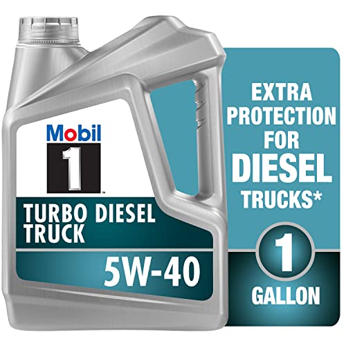
- Mobil 1
 Turbo Diesel Truck Is Designed For Modern Diesel Truck Engines, Delivering Long Drain Capability, Exceptional Performance, And Potential Fuel Economy Benefits
 - Meets Or Exceeds The Demanding Specifications Of Major Truck Manufacturers - One Engine Oil Can Be Used For Mixed Fleet Operations
- Recommended For Use In All Super High-Performance Diesel Applications, Including Low Emission Engines
- Helps Engines Last Longer By Reducing Low-Temperature Sludge Buildup And High-Temperature Deposits
 Turbo Diesel Truck Is Designed For Modern Diesel Truck Engines, Delivering Long Drain Capability, Exceptional Performance, And Potential Fuel Economy Benefits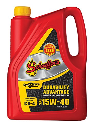
- Excellent wear protection during severe operating conditions
- Oil durability: strong oxidation and viscosity control with less oil consumption
- Better contamination control with superior soot-busting, deposit-dispersing capability
- Strong stay-in-grade performance throughout the life of the oil
- Friction modified with micron moly and penetrate

- Synthetic blend 15W-40 diesel engine oil with Triple Protection Plus technology protects against wear, deposits, and oil breakdown
- Ideal for on-highway fleets, construction, and agricultural machinery, and diesel pickup trucks — including high-power vehicles that require resistance to heat and stress
- Triple Protection Plus technology offers better low-temperature flow, which delivers excellent equipment protection, long engine life, and maintains viscosity control under high temperatures
- Delivers good engine cleanliness and protection against piston deposits, ensuring engine and component reliability at extended oil drain intervals
- Advanced low-ash formulation helps control the blocking or poisoning of exhaust after-treatment devices, helping maintain vehicle emission compliance and engine fuel efficiency
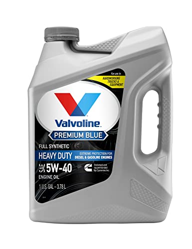
- EXCELLENT WEAR PROTECTION IN HEAVY DUTY APPLICATIONS that can take a toll on critical internal moving parts
- RESISTS OXIDATION AND FIGHTS DEPOSITS & SLUDGE with higher quality synthetic base oils and special inhibitors
- PROTECTS DURING COLD START UPS WHILE CONTROLING SOOT as heavy-duty equipment can sit idle for extended periods of time
- ADVANCED FUEL ECONOMY up to 1.5% over 15W-40 conventional oils in on-highway operations
- UNIQUE 5,000 MILES OIL DRAINS EXTENSION in Cummins X15/X12 engines when average is 7mpg or higher
This product presentation was made with AAWP plugin.