
NHTSA ID Number: 10128680
Manufacturer Communication Number: SMB178
Summary
This Service Manual Bulletin provides new OEM (Kongsberg) PM inspection requirements and new installation procedure for the adjustable floor pedal moveable arm on specifically equipped vehicles.
359 Affected Products
Vehicles
NEW FLYER | 40BRT | 2014 |
| NEW FLYER | 40LFA | 2010 |
| NEW FLYER | 40SF | 2010 |
| NEW FLYER | C30LF | 2001-2002, 2004-2005 |
| NEW FLYER | C35LF | 1998-1999, 2001-2002, 2004-2009 |
| NEW FLYER | C35LFR | 2009-2012 |
| NEW FLYER | C40FLR | 2012 |
| NEW FLYER | C40HF | 1995-1997 |
| NEW FLYER | C40LF | 1994-2013 |
| NEW FLYER | C40LFR | 2006-2013 |
| NEW FLYER | D30LF | 1996-2000, 2003-2005 |
| NEW FLYER | D35HF | 1988-1996 |
| NEW FLYER | D35LF | 1995-2010 |
| NEW FLYER | D35LFR | 2007, 2009-2012 |
| NEW FLYER | D40HF | 1988-1994 |
| NEW FLYER | D40I | 2004-2006 |
| NEW FLYER | D40LF | 1994-2010 |
| NEW FLYER | D40LFA | 2010 |
| NEW FLYER | D40LFR | 2005-2013 |
| NEW FLYER | D41LF | 2006-2008 |
| NEW FLYER | D41LFR | 2008 |
| NEW FLYER | D45S | 1999-2002 |
| NEW FLYER | D60HF | 1988-2007 |
| NEW FLYER | D60LF | 1998-2000, 2002-2009 |
| NEW FLYER | D60LFA | 2006, 2008-2009 |
| NEW FLYER | D60LFR | 2002-2013 |
| NEW FLYER | D61LFR | 2007-2008 |
| NEW FLYER | DE30LFR | 2010 |
| NEW FLYER | DE35LF | 2005, 2007-2010 |
| NEW FLYER | DE35LFA | 2009 |
| NEW FLYER | DE35LFR | 2007, 2010-2011 |
| NEW FLYER | DE40I | 2005-2006 |
| NEW FLYER | DE40LF | 2004-2010 |
| NEW FLYER | DE40LFA | 2008-2010 |
| NEW FLYER | DE40LFR | 2006-2011 |
| NEW FLYER | DE41LF | 2006-2008 |
| NEW FLYER | DE41LFR | 2006-2008 |
| NEW FLYER | DE60LF | 2004-2006, 2008-2010 |
| NEW FLYER | DE60LFA | 2005-2007, 2009-2011 |
| NEW FLYER | DE60LFR | 2004, 2007-2013 |
| NEW FLYER | DE61LF | 2008 |
| NEW FLYER | E40LFR | 2008-2009 |
| NEW FLYER | E60HF | 1992-1994 |
| NEW FLYER | GE35LFR | 2008-2010 |
| NEW FLYER | GE40LF | 2004-2010 |
| NEW FLYER | GE40LFA | 2008 |
| NEW FLYER | GE40LFR | 2008-2010 |
| NEW FLYER | GE41LRF | 2008 |
| NEW FLYER | H40LFR | 2007 |
| NEW FLYER | INVERO | 2005-2006 |
| NEW FLYER | L40HF | 1994-1995 |
| NEW FLYER | L40LF | 1998, 2004-2006 |
| NEW FLYER | L40LFR | 2009 |
| NEW FLYER | MD30 | 2014-2016 |
| NEW FLYER | MD35 | 2015-2016 |
| NEW FLYER | XCELSIOR | 2008-2017 |
| NEW FLYER | XD35 | 2010-2017 |
| NEW FLYER | XD40 | 2010-2017 |
| NEW FLYER | XD60 | 2012-2017 |
| NEW FLYER | XDE35 | 2010-2017 |
| NEW FLYER | XDE40 | 2009-2017 |
| NEW FLYER | XDE60 | 2013-2017 |
| NEW FLYER | XE40 | 2013-2015 |
| NEW FLYER | XN35 | 2013-2017 |
| NEW FLYER | XN40 | 2011-2018 |
| NEW FLYER | XN60 | 2010-2017 |
| NEW FLYER | XT40 | 2014-2016 |
| NEW FLYER | XT60 | 2014-2017 |
SMB-178
ISSUE DATE: Jan 05 2018
Adjustable Floor Pedal System
PM – PREVENTIVE MAINTENANCE
This bulletin provides new PM inspection requirements to be performed at the 24,000 mile (38,600 km) interval, and new installation procedures for the moveable arm on the brake and accelerator assembly installed on your New Flyer vehicle.
Refer to PMB-049 for replacement parts.
Make this Service Bulletin available to service personnel to inform them of changed information.
SEOCONTENT-START
SMB-178 1 of 5
SERVICE MANUAL BULLETIN
This Service Manual Bulletin is prepared by the Publications Department of New Flyer Industries
Canada ULC. Refer to details below.
The New Flyer vehicles described in this manual may be protected by one or more
patents and design applications or registrations in the United States and Canada,
and in other countries. Refer to “Vehicle Patent Information” in this manual.
Copyright © 2018 New Flyer Industries Canada ULC
ISSUE DATE: Jan 05 2018
SMB-178
APPLICABILITY
VEHICLE LENGTH 30ft. 35ft. 40ft. 60ft. ALL
VEHICLE TYPE
Xcelsior® MiDi® Invero®
ALL
Low Floor High Floor
FUEL TYPE
Diesel Diesel/Electric CNG LNG
ALL
Fuel Cell Trolley/Electric Battery/Electric
SUBJECT Adjustable Floor Pedal System
SECTION TITLE PM – PREVENTIVE MAINTENANCE
DETAILS This bulletin provides new PM inspection requirements to be performed
at the 24,000 mile (38,600 km) interval, and new installation procedures
for the moveable arm on the brake and accelerator assembly installed on
your New Flyer vehicle.
Refer to PMB-049 for replacement parts.
Make this Service Bulletin available to service personnel to inform them
of changed information.
2 of 5 SMB-178
SERVICE MANUAL BULLETIN
SMB-178
The New Flyer vehicles described in this manual may be protected by one or more
patents and design applications or registrations in the United States and Canada,
and in other countries. Refer to “Vehicle Patent Information” in this manual.
Copyright © 2018 New Flyer Industries Canada ULC
1. Movable Arm Inspection
Inspect the moveable arm for cracks every
24,000 miles (38,600 km), 3 months, or
900 operating hours, whichever occurs
first.
☞NOTE:
This maintenance interval may need to be
adjusted to suit the specific operating conditions
and geographic location. Exposure
to slush, salt, and/or sand will require more
frequent inspection. If the unit is subjected
to spray or pressure washing, then it will be
necessary to relubricate immediately following
cleaning.
1. Remove the brake treadle. Refer to your
New Flyer Service Manual for removal procedure.
2. With the brake treadle removed, rotate the
moveable arm up such that it sits in a
nearly vertical position and the steel plate
on the underside is easily visible. See “Fig.
1: Moveable Arm Inspection” on page 3.
DO NOT remove the moveable arm
assembly unless replacing with maintenance
kit. Refer to PMB-049 for kit part
number.
Read warnings and follow guidelines
printed on Dynaflux chemical containers.
3. While wearing safety glasses and gloves,
liberally spray Dynaflux CNF315-16
cleaner onto a clean cloth so as to saturate
a small area of the cloth.
4. Use the cloth to clean the exposed surface
of the steel plate on the moveable arm. All
dirt and grease needs to be removed.
Dynaflux cleaner may be applied directly to
the plate if needed.
DO NOT loosen screws or remove the
steel plate from the moveable arm casting.
5. Allow 5 minutes for the cleaner to evaporate
such that the plate on the moveable
arm is completely dry and clean.
The red penetrant may stain skin if not
protected.
6. While wearing latex gloves and safety
glasses, spray a medium wet coat of
Dynaflux PHF315-16 penetrant onto the
surface of the steel plate.
☞NOTE:
Avoid excess overspray on nearby components.
7. Allow the penetrant to soak for a minimum
of 10 minutes.
8. Saturate an area of a clean cloth with
Dynaflux cleaner and thoroughly wipe
away the penetrant from the steel plate.
☞NOTE:
DO NOT spray cleaner directly onto the
plate.
9. Allow 5 minutes for the cleaner to evaporate,
and then apply an even coat of
Dynaflux DNF315-16 developer to the
steel plate.
SMB-178 3 of 5
SERVICE MANUAL BULLETIN
SMB-178
The New Flyer vehicles described in this manual may be protected by one or more
patents and design applications or registrations in the United States and Canada,
and in other countries. Refer to “Vehicle Patent Information” in this manual.
Copyright © 2018 New Flyer Industries Canada ULC
10.Allow the developer to sit for a minimum of
10 minutes.
11.Carefully inspect the plate for any red lines
on the plate surface. These red lines indicate
the presence and location of cracks in
the steel material.
12.If any cracks are found, replace the moveable
arm. Refer to 2. “Moveable Arm
Replacement” on page 4 of this bulletin for
procedure.
13.If no cracks are detected, clean off remaining
penetrant and developer from the steel
plate, moveable arm, and surrounding
area using a cloth and Dynaflux cleaner.
DO NOT remove grease from or apply
cleaner to the ball bearing on the moveable
arm or the brake plunger.
14.Apply a thin coat of new grease (KA
6705212 / Bendix 246671) to the steel
plate.
Use only the grease specified. This is a
very specific grease that has been fully
tested and approved for this application
and cannot be substituted with any
other grease.
15.Rotate the moveable arm down to its normal
horizontal position such that it rests
against the brake plunger.
16.Reinstall the brake treadle. Refer to Section
19 of your New Flyer Service Manual
for installation procedure.
Fig. 1: Moveable Arm Inspection
????????????????????????????????????????????
????????????????????????????????????????????
s030719a.svg
4 of 5 SMB-178
SERVICE MANUAL BULLETIN
SMB-178
The New Flyer vehicles described in this manual may be protected by one or more
patents and design applications or registrations in the United States and Canada,
and in other countries. Refer to “Vehicle Patent Information” in this manual.
Copyright © 2018 New Flyer Industries Canada ULC
2. Moveable Arm Replacement
2.1. Removal
1. Remove the brake treadle.
2. Remove the cover by removing the two
Philips head screws. See “Fig. 2: Moveable
Arm Removal” on page 4.
3. Remove the safety clip from the moveable
arm pivot pin.
4. Remove the moveable arm pivot pin by
sliding it out of the moveable arm and carrier.
5. Remove the moveable arm.
6. Dispose of the old safety clip, moveable
arm pivot pin, and moveable arm. They
should not be reused.
Fig. 2: Moveable Arm Removal
????????????????????????????????????????????????
????????????????????????
????????????????????????????
????????????
????????????????????
????????????????????????????????????
????????????????????????????????????????????
s030720a.svg
SMB-178 5 of 5
SERVICE MANUAL BULLETIN
SMB-178
The New Flyer vehicles described in this manual may be protected by one or more
patents and design applications or registrations in the United States and Canada,
and in other countries. Refer to “Vehicle Patent Information” in this manual.
Copyright © 2018 New Flyer Industries Canada ULC
2.2. Installation
1. Align new moveable arm to holes in carrier
and insert new moveable arm pivot pin
with the head facing the brake treadle as
shown.
2. Install a new safety clip to the moveable
arm pivot pin. See “Fig. 2: Moveable Arm
Removal” on page 4.
☞NOTE
When properly engaged, the safety clip will
exhibit an audible “snap”.
The safety clip must be fully seated
around the end of the moveable arm
pivot pin. Failure to fully seat and lock
the safety clip in place could allow the
moveable arm pivot pin to shift and
cause a binding condition of the moveable
arm. ALWAYS check to make sure
the safety clip is fully seated and locked
over the end of the moveable arm pivot
pin.
3. Inspect the safety clip to make sure it is
secured correctly to the moveable arm
pivot pin as follows: See “Fig. 3: Moveable
Arm Safety Clip” on page 5.
a. Pull on the safety clip to ensure it is
engaged.
4. Push or pull on the pivot pin to ensure it
cannot be removed.
5. Install cover onto carrier using two Phillips
head screws
6. Tighten each screw to 31 in-lb. ± 4.5 (3.5
Nm ± 0.5)
7. Reinstall the brake treadle. Refer to Section
19 of your New Flyer Service Manual
for installation procedure.
Fig. 3: Moveable Arm Safety Clip
????????????????????????????????????????????
????????????????????????????????????
????????????????????????????
????????????????????????????????????
????????????????????????????????????????????
s030721a.svg
SMB178
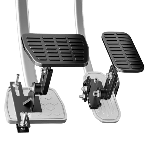
- 【DESIGNED FOR SHORT DRIVERS】Designed to provide additional pedal reach for shorter drivers who want greater flexibility in their seating position. The extended pedals help bring the accelerator and brake closer while maintaining a comfortable driving position
- 【ADJUSTABLE LENGTH & ANGLE】Customize the pedal position according to your driving needs and leg length. The brake pedal extension adjusts from 1.2 to 2.3 inches, while the accelerator extension adjusts from 1.7 to 3.5 inches, offering flexible positioning compared with fixed pedal extensions
- 【DURABLE METAL CONSTRUCTION】Made with sturdy metal components for reliable everyday use. The extended pedal surfaces feature a textured, non-slip design to help provide secure foot contact and a stable pedal feel during acceleration and braking
- 【GAS & BRAKE PEDAL EXTENDER KIT】Designed for both accelerator and brake pedals, this kit allows you to adjust pedal reach without permanently modifying the vehicle. The adjustable design provides greater flexibility for different pedal positions and driving preferences
- 【EASY TO INSTALL & ADJUST】The included hardware makes installation and adjustment straightforward, with no permanent vehicle modification required. Please measure your original pedals and check available clearance before purchase to ensure compatibility.
- This pedal extender kit is specially designed to deliver hassle-free convenience for short drivers, letting them operate their vehicles comfortably and without any driving obstacles.
- Boasting universal compatibility, it fits the majority of vehicle models (note: not all vehicles are compatible) and works with various pedal styles, while locking firmly onto your car’s pedals. Both the angle and length of the extenders are adjustable to perfectly accommodate the needs of short-stature drivers.
- Constructed with a premium all-metal frame, the extenders are made of strengthened steel, and their pedal surfaces are covered with anti-slip rubber to ensure stable operation.
- Installation and adjustment are easy to handle—just follow the step-by-step instructions in the detailed user manual that comes with your purchase.
- Please note: A basic level of mechanical knowledge is required for proper installation and adjustment. If you encounter difficulties when installing the extenders on your own, please refer to the user manual, watch the listing’s instructional videos, or consult a local professional mechanic for assistance.

- Extend the Pedals: Tailored for short drivers to drive comfortably and smoothly, eliminating reach issues and enhancing safety on the road.
- Universal Fit: Compatible with most vehicles and various pedal types. Fully adjustable in both length and angle for a customized driving position.
- All Metal Construction: Built from enhanced heavy-duty steel for maximum durability, featuring anti-slip rubber pads for a secure grip.
- Easy to Adjust: Simple installation and adjustment process. Comes with a clear user manual to guide you through the setup effortlessly.
- Professional Guidance: Requires basic mechanical skills to install. Please consult the manual, listing video, or a local mechanic if needed.
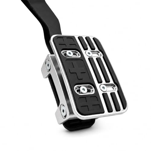
- Improves Pedal Reach – Extends the accelerator pedal for smoother heel-toe transitions and reduced foot strain during driving.
- Adjustable Height Options – Choose 20 mm or 35 mm raise to match your brake-to-gas pedal drop precisely.
- Durable Construction – Made from sturdy aluminum alloy with black TPU anti-slip pads for secure and reliable grip.
- Easy Installation – Simple bolt-on design with adjustable clamp (40–60 mm range) fits factory pedal width, no modification required.
- Wide Compatibility – Designed for Honda Civic, Accord, CR‑V / CR‑V Hybrid, HR‑V, Passport, Pilot, Odyssey, and Ridgeline ,Fits Most Honda Models.

- Adjustable Length and Height:Our accelerator and brake pedal extenders feature an adjustable design,allowing you to customize the length and height according to your preference.This ensures a comfortable driving experience for individuals of all heights,especially short drivers.
- Steel and Rubber Construction:Made from high-quality steel and rubber materials,our pedal extenders are built to last.The durable construction ensures long-term reliability and stability.
- Non-Slip Safety:The rubber surface provides excellent grip, preventing your feet from slipping off the pedals, even in wet or slippery conditions.
- Easy Installation:Installing our pedal extenders is a breeze.Place the installed accessories directly on the pedal, adjust the position, and tighten the screws.
- Wide Application:Our pedal extenders are suitable for various vehicles, including cars, go-karts, and more.
This product presentation was made with AAWP plugin.