
NHTSA ID Number: 10162337
Manufacturer Communication Number: Odyne Service Bu
Summary
Odyne Systems, LLC has issued a service bulletin – FSA 00029E Installation of Driveshaft Loop to address u-joint or driveline failure (In case of failure, driveshaft loop limits movement of PTO Driveshaft)
23 Affected Products
Vehicles
| MAKE | MODEL | YEAR |
FORD | F-750 | 2014 |
| FREIGHTLINER | 1085D | 2014 |
| FREIGHTLINER | 114SD | 2014, 2018 |
| FREIGHTLINER | M2 | 2014-2015, 2017 |
| INTERNATIONAL HARVESTER | 7400 | 9999 |
| INTERNATIONAL HARVESTER | 7500 | 9999 |
| INTERNATIONAL | 4300 | 2011, 2018 |
| INTERNATIONAL | 4400 | 2014-2017 |
| KENWORTH | K370 | 2014, 2017 |
| KENWORTH | T370 | 2014-2017 |
| PETERBILT | 337 | 2018 |
| PETERBILT | 348 | 2018 |
Title: INSTALLATION OF DRIVESHAFT LOOP
Issue: In case of u-joint or driveline failure, driveshaft loop limits movement of PTO driveshaft.
Special Tools or Software Required:
| Where Available | Type of Tool | Equipment Description |
| 5/8 socket | 10mm socket | |
| 11/16 wrench | T10 torx | |
| External torx E6 | 15mm socket |
Action:
Remove Driveline from Traction Motor. Install updated Driveline Loop
Before Starting Procedure: Disconnect hybrid Battery, remove key from ignition and store in a safe place.
Service Procedure:
Reference: The diagram’s below shows the relative positions of the Odyne PTO (Power Take Off), Driveline, Plates, Hub, and Motor. Parts vary based off model year and production release.
Driveline Removal / Driveline Loop & Driveline Shaft Install
- Remove existing 8 cap screws from Remy motor face.
a. G2V1-G2V5
Install lock washers (30244) on cap screws OEM Cap screws (3) & 30253 (5). Add Blue Loctite to all fasteners and set them aside ready for install. Take your driveline loop (40712) have it ready.
b. G2V6-CURRENT PRODUCTION
Install lock washers (30244) on cap screws (30245 & 30252). Add Blue Loctite to all fasteners and set them aside ready for install. Take your stack plate assembly, stack ring (40703), and driveline loop (40712) have them ready. Place your spline on the hub to the spline of the motor on your bearing/hub assembly. Seat the ring, and plate to motor when the spline engages. Start your bottom three fasteners on the plate to hold the assembly in place, take note of the grease Zerk, point the Zerk where it is accessible. Start the cap screws (30245) and just tighten slightly, leaving clearance, and room to move it accordingly for the other fasteners.
a. G2V1-G2V5
Place your driveline loop bracket in front of the motor and finger tighten the fasteners (30253) until all of our fasteners are started around the drive loop. (Driveline Loop configuration changes per application) If you need to rotate the loop accordingly to accommodate for frame/routing demands it is permissible.
b. G2V6-CURRENT PRODUCTION
Place your driveline loop bracket in front of the bearing plate and finger tighten the fasteners (30252) until all fasteners are started. (Driveline Loop configuration changes per application) If you need to rotate the loop accordingly to accommodate for frame/routing demands it is permissible.
- Torque the fasteners to 10 foot pounds in a cross torque pattern. (ALL VERSIONS)
- Verify that the assembly spins freely. Once you have verified that your assembly moves freely, finish torque the fasteners in a cross pattern (referenced previously) to 22 ft. pounds. You are now ready to install your drive shaft.
- Reinstall the driveline using bolts (30187) and washer (30189) and nut (30188) on the PTO flange. Apply red Loctite to the bolt threads and torque to 37ft-lbs.
- Reinstall the driveline using bolts (30247) and washer (30189) on the Hub/back fasteners of the driveline. Apply red Loctite to the bolt threads and torque to 37ft-lbs.
- Check driveline for movement/typical mechanical wear. Please reach out to your Odyne service representative for additional assistance or parts.
You have now completed your Driveline Loop install
Test Truck and Return Parts
- Test the truck to make sure everything works properly in driving mode, and when stationary with ePTO running the hydraulic pump or air compressor.
Parts Required:
| Part Number | Description | Quantity |
| Shop Supply | Blue Loctite | 1 |
| 40712 | Driveline Loop | 1 |
| 30244 | WASHER,SPLIT LOCK M10, SS | 5 |
| 30253 | SCREW,CAP, M10-1.5X35, SS | 5 |
| 90052 | Driveline Loop Hardware | 1 |
Warranty Information:
| Code | Description | Time |
| 00029E | Installation of Driveshaft Loop | 1.0 |
DRIVESHAFT LOOP INSTALL
00029E
Doc Rev 06.28.19
SEOCONTENT-START
SERVICE BULLETIN
The information in Technical Service Bulletins is intended for use by trained, professional technicians with the knowledge, tools, and equipment to do
the job properly and safely. It informs these technicians of conditions that may occur on some vehicles, or provides information that could assist in
proper vehicle service. Warranty Policy documentation determines Warranty coverage unless stated otherwise in the TSB article. The information in
this Technical Service Bulletin (TSB) was current at the time of printing. Odyne Systems, LLC reserves the right to supersede this information with
updates. The most recent information is available through Odyne on-line technical resources.
P a g e | 1
DRIVESHAFT LOOP INSTALL
00029E Doc Rev 06.28.19
Title: INSTALLATION OF DRIVESHAFT LOOP
Issue: In case of u-joint or driveline failure, driveshaft loop limits movement of PTO driveshaft.
Applies To:
System
Date of Issue
Bulletin Number
Bulletin Type
Odyne Systems
06/28/2019
0029E
☒ Field Service Action
☐ Technical Service Bulletin
☐ Technical Service Advisory
3FRYX7FE6CV353240
1HTMMAAN8EH068239
3ALACYDT6EDFV2462
1HTMMAAN09H130576
3FRYX7FE6CV353237
1HTMMAAN4EH068240
1FVACXDTXHHJH3093
1HTMMAAN09H130577
3FRYF7FEXCV353244
1HTMMAAN6EH068241
1FVACXFCXJHJM8931
2NP3KJ8X8JM491025
3FRYX7FL2DV026110
1HTMMAAN8EH068242
1FVACXFC1JHJM8932
2NP2HJ8X4KM617604
3FRYX7FE8CV353241
1HTMMAAN9EH068234
1FVACXFC7JHJM9065
2NP2HJ8X6KM617605
3FRYX7FEXCV353242
1HTWGAAR7EH095922
1FVACYDT8FHGJ5833
2NP2HJ8X8KM617606
3FRYX7FEXCV353239
1HTWGAAR9EH095923
1FVACYDTXFHGJ5834
2NP2HJ8XXKM617607
3FRYX7FE8CV353238
1HTWGAAR5EH105251
1FVACYDT1FHGJ5835
1FVACYDT4BDAY7502
3FRYX7FE2CV353235
1HTWGAAR9EH105253
3HAMKAAR5FL111908
1FVACYDT6BDAY7503
3FRYX7FE0CV353234
1HTWGAAR9CJ547228
1FVACYDT7FHGD3350
1FVACYDT7FHGE2548
3FRYF7FE3CV353246
1HTWGAAR7EH105252
1FVACYDT9FHGD3351
1FVACYDT9FHGE2549
3FRYF7FE1CV353245
3HAWGSTT2HL672529
1FVACYDT0FHGD3352
2NKHHJ8X6JM196063
3FRYF7FE8CV353243
3HAWGSTT9HL672530
1FVACYDT2FHGF2906
2NKHHJ8X7GN491214
3FRYF7FL8DV026101
3HAWGSTT0HL672531
1FVACYDT4FHGF2907
2NKHHJ8X5HM147303
3FRYF7FLXDV026102
3HAWGSTT2HL672532
1FVACYDT0FHGD3349
2NKHHJ8X7HM147304
3FRYX7FL5DV026103
3HAWGSTT4HL672533
3HAMMMMNXFL522970
1FVACXDT3FHGT1383
3FRYX7FL7DV026104
3HAWGSTT2HL672692
3HAMMMMN3FL522969
1FVHG3DV6FHGE0054
3FRYX7FL9DV026105
3HAWGSTT1HL672537
1FVHG5CY9FHGE5871
1FVHG3DV4FHGE0053
SERVICE BULLETIN
The information in Technical Service Bulletins is intended for use by trained, professional technicians with the knowledge, tools, and equipment to do
the job properly and safely. It informs these technicians of conditions that may occur on some vehicles, or provides information that could assist in
proper vehicle service. Warranty Policy documentation determines Warranty coverage unless stated otherwise in the TSB article. The information in
this Technical Service Bulletin (TSB) was current at the time of printing. Odyne Systems, LLC reserves the right to supersede this information with
updates. The most recent information is available through Odyne on-line technical resources.
P a g e | 2
DRIVESHAFT LOOP INSTALL
00029E Doc Rev 06.28.19
Special Tools or Software Required:
Where Available Type of Tool Equipment Description
5/8 socket 10mm socket
11/16 wrench T10 torx
External torx E6 15mm socket
Action:
Remove Driveline from Traction Motor. Install updated Driveline Loop
3FRYX7FL0DV026106 3HAWGSTT3HL672538 1FVHG5CY0FHGE5872 1FVAC5FE4JHJH7973
3FRYX7FL2DV026107 3ALACYDTXEDFV2464 3FRYF7FL1DV061076 1FVAC5FE6JHJH7974
3FRYX7FL4DV026108 1FVACYDT7EHFV5672 3FRYF7FLXDV061075 1FVAC5FE8JHJH7975
3FRYX7FL6DV026109 1FVACXDT6HHJH3091 3FRYF7FL6DV061073 1FVAC5FEXJHJH7976
3ALACXDT6EDFX9591 1HTMMAAR4AH176726 3FRYF7FL4DV061072 1FVAC5FE1JHJH7977
3HAZZMMR2JL594877 1HTWGAZR3FH617144 2NKHHJ8X4EM418900 1FVAC5FE3JHJH7978
1HTMMMMRXKH554319 1HTZZAAR8CH549387 2NKHHJ8X1EM418899 1FVHG3DV8FHGE0055
3FRXF7FK6CV431150 1HTMMAARX9H133102 1HTJTSKR9EH052340 3HAMMAAR2DL233150
1FVACXDT8HHJE2649 3HAMMAAN7CL456652 3HAWCAAR8FL690012 1FVHG3FE1JHJW7915
1FVACXDT6HHJE2648 1HTZZAAR9CH549415 1FVACXDT4EHFZ4035 1FVHG3FE3JHJW7916
1HTMMAAR1AH271521 1HTMMAANXFH526106 1FVACYCY0EHFX1130 1FVHG3FE5JHJW7917
1HTMMAAN0CH081788 1HTMMAAR3FH526161 1FVACXDT0FHGJ3519 1FVHG3FE7JHJW7918
1HTMMAAN5EH073771 1HTMKSTN4HH732811 1FVACXDT7FHGJ3520 3HAWNAZT6FL560823
1HTMMAAN7EH073772 3HAMKSTN5JL578402 3FRXF7FG5FV671211 3HAWNAZT8FL560824
1HTMMAAN9EH073773 1HTEUMMN3KH717118 1FVACXDT0EHFU8251 1HTWDAAR19J125195
1HTMMAAN0EH073774 3HAMKAARXFL127540 1FVACXDT8EHFU8241 1HTWDAARX9J120867
1HTMMAAN2EH073775 3HAMKAAR3FL127542 1HTMKAZRXEH783343 1HTWXAHT58J652843
1HTMMAAN6EH029178 1FVACYCY8FHGE8002 3HAMMAAN5GL744336 1FUYDZYB3PH496580
1HTMMAAN0EH068235 3FRXF7FJ6FV679474 1FVHCYCY1FHGG7828 1FVACXDT9EHFT2453
1HTMMAAN2EH068236 1HTWGAZT0FH518065 1FVHCYCYXFHGG7827 3HAMKAZN5EL013882
1HTMMAAN4EH068237 1FVACXCY3FHGE4465 3BKJHM7X7HF581538
1HTMMAAN6EH068238 3ALACYDT8EDFV2463 3BKJHM7X5HF581408
SERVICE BULLETIN
The information in Technical Service Bulletins is intended for use by trained, professional technicians with the knowledge, tools, and equipment to do
the job properly and safely. It informs these technicians of conditions that may occur on some vehicles, or provides information that could assist in
proper vehicle service. Warranty Policy documentation determines Warranty coverage unless stated otherwise in the TSB article. The information in
this Technical Service Bulletin (TSB) was current at the time of printing. Odyne Systems, LLC reserves the right to supersede this information with
updates. The most recent information is available through Odyne on-line technical resources.
P a g e | 3
DRIVESHAFT LOOP INSTALL
00029E Doc Rev 06.28.19
Before Starting Procedure: Disconnect hybrid Battery, remove key from ignition and store in a safe place.
Service Procedure:
Reference: The diagram’s below shows the relative positions of the Odyne PTO (Power Take Off), Driveline, Plates, Hub, and Motor. Parts vary based off model year and production release.
G2V1-G2V5
Driveshaft Loop
OEM Hardware
30253
Lovejoy Set screws
Motor
SERVICE BULLETIN
The information in Technical Service Bulletins is intended for use by trained, professional technicians with the knowledge, tools, and equipment to do
the job properly and safely. It informs these technicians of conditions that may occur on some vehicles, or provides information that could assist in
proper vehicle service. Warranty Policy documentation determines Warranty coverage unless stated otherwise in the TSB article. The information in
this Technical Service Bulletin (TSB) was current at the time of printing. Odyne Systems, LLC reserves the right to supersede this information with
updates. The most recent information is available through Odyne on-line technical resources.
P a g e | 4
DRIVESHAFT LOOP INSTALL
00029E Doc Rev 06.28.19
G2V6 –Current Production
Dampened Driveshaft
(Optional)
Splined hub
(Optional)
Lovejoy Set screws
Motor
Grease Zerk location
(Optional)
Pillow Bearing
(Optional)
Driveshaft Loop
SERVICE BULLETIN
The information in Technical Service Bulletins is intended for use by trained, professional technicians with the knowledge, tools, and equipment to do
the job properly and safely. It informs these technicians of conditions that may occur on some vehicles, or provides information that could assist in
proper vehicle service. Warranty Policy documentation determines Warranty coverage unless stated otherwise in the TSB article. The information in
this Technical Service Bulletin (TSB) was current at the time of printing. Odyne Systems, LLC reserves the right to supersede this information with
updates. The most recent information is available through Odyne on-line technical resources.
P a g e | 5
DRIVESHAFT LOOP INSTALL
00029E Doc Rev 06.28.19
Driveline Removal / Driveline Loop & Driveline Shaft Install
1. Remove existing 8 cap screws from Remy motor face.
2.
a. G2V1-G2V5
Install lock washers (30244) on cap screws OEM Cap screws (3) & 30253 (5). Add Blue Loctite to all fasteners and set them aside ready for install. Take your driveline loop (40712) have it ready.
b. G2V6-CURRENT PRODUCTION
Install lock washers (30244) on cap screws (30245 & 30252). Add Blue Loctite to all fasteners and set them aside ready for install. Take your stack plate assembly, stack ring (40703), and driveline loop (40712) have them ready. Place your spline on the hub to the spline of the motor on your bearing/hub assembly. Seat the ring, and plate to motor when the spline engages. Start your bottom three fasteners on the plate to hold the assembly in place, take note of the grease Zerk, point the Zerk where it is accessible. Start the cap screws (30245) and just tighten slightly, leaving clearance, and room to move it accordingly for the other fasteners.
3.
a. G2V1-G2V5
Place your driveline loop bracket in front of the motor and finger tighten the fasteners (30253) until all of our fasteners are started around the drive loop. (Driveline Loop configuration changes per application) If you need to rotate the loop accordingly to accommodate for frame/routing demands it is permissible.
SERVICE BULLETIN
The information in Technical Service Bulletins is intended for use by trained, professional technicians with the knowledge, tools, and equipment to do
the job properly and safely. It informs these technicians of conditions that may occur on some vehicles, or provides information that could assist in
proper vehicle service. Warranty Policy documentation determines Warranty coverage unless stated otherwise in the TSB article. The information in
this Technical Service Bulletin (TSB) was current at the time of printing. Odyne Systems, LLC reserves the right to supersede this information with
updates. The most recent information is available through Odyne on-line technical resources.
P a g e | 6
DRIVESHAFT LOOP INSTALL
00029E Doc Rev 06.28.19
b. G2V6-CURRENT PRODUCTION
Place your driveline loop bracket in front of the bearing plate and finger tighten the fasteners (30252) until all fasteners are started. (Driveline Loop configuration changes per application) If you need to rotate the loop accordingly to accommodate for frame/routing demands it is permissible.
30253
OEM HARDWARE
SERVICE BULLETIN
The information in Technical Service Bulletins is intended for use by trained, professional technicians with the knowledge, tools, and equipment to do
the job properly and safely. It informs these technicians of conditions that may occur on some vehicles, or provides information that could assist in
proper vehicle service. Warranty Policy documentation determines Warranty coverage unless stated otherwise in the TSB article. The information in
this Technical Service Bulletin (TSB) was current at the time of printing. Odyne Systems, LLC reserves the right to supersede this information with
updates. The most recent information is available through Odyne on-line technical resources.
P a g e | 7
DRIVESHAFT LOOP INSTALL
00029E Doc Rev 06.28.19
4. Torque the fasteners to 10 foot pounds in a cross torque pattern. (ALL VERSIONS)
30245
30252
SERVICE BULLETIN
The information in Technical Service Bulletins is intended for use by trained, professional technicians with the knowledge, tools, and equipment to do
the job properly and safely. It informs these technicians of conditions that may occur on some vehicles, or provides information that could assist in
proper vehicle service. Warranty Policy documentation determines Warranty coverage unless stated otherwise in the TSB article. The information in
this Technical Service Bulletin (TSB) was current at the time of printing. Odyne Systems, LLC reserves the right to supersede this information with
updates. The most recent information is available through Odyne on-line technical resources.
P a g e | 8
DRIVESHAFT LOOP INSTALL
00029E Doc Rev 06.28.19
5. Verify that the assembly spins freely. Once you have verified that your assembly moves freely, finish torque the fasteners in a cross pattern (referenced previously) to 22 ft. pounds. You are now ready to install your drive shaft.
6. Reinstall the driveline using bolts (30187) and washer (30189) and nut (30188) on the PTO flange. Apply red Loctite to the bolt threads and torque to 37ft-lbs.
7. Reinstall the driveline using bolts (30247) and washer (30189) on the Hub/back fasteners of the driveline. Apply red Loctite to the bolt threads and torque to 37ft-lbs.
8. Check driveline for movement/typical mechanical wear. Please reach out to your Odyne service representative for additional assistance or parts.
You have now completed your Driveline Loop install
Test Truck and Return Parts
1. Test the truck to make sure everything works properly in driving mode, and when stationary with ePTO running the hydraulic pump or air compressor.
SERVICE BULLETIN
The information in Technical Service Bulletins is intended for use by trained, professional technicians with the knowledge, tools, and equipment to do
the job properly and safely. It informs these technicians of conditions that may occur on some vehicles, or provides information that could assist in
proper vehicle service. Warranty Policy documentation determines Warranty coverage unless stated otherwise in the TSB article. The information in
this Technical Service Bulletin (TSB) was current at the time of printing. Odyne Systems, LLC reserves the right to supersede this information with
updates. The most recent information is available through Odyne on-line technical resources.
P a g e | 9
DRIVESHAFT LOOP INSTALL
00029E Doc Rev 06.28.19
Parts Required:
Part Number
Description
Quantity
Shop Supply
Blue Loctite
1
40712
Driveline Loop
1
30244
WASHER,SPLIT LOCK M10, SS
5
30253
SCREW,CAP, M10-1.5X35, SS
5
90052
Driveline Loop Hardware
1
Warranty Information:
Code
Description
Time
00029E
Installation of Driveshaft Loop
1.0
Odyne Service Support Resources:
To request technical assistance, contact [email protected].
To request parts, contact [email protected].
1 Associated Document
Manufacturer Communications
MC-10162337-9999.pdf 806.872KB

- ❤ [Equipped with Nema 14-50 plug 240V, Compatible with 110-120V Nema 5-15p to 14-50r EV Adapter(Not packaged) or the other EV Adapter Cable]: Suggest install the 240V Nema 14-50 plug-in socket. [Kindly Note When Using the 5-15P Adapter]: 1. The RV Adapter cable doesn't work for EV chargers, please order the correct EV adapter cable. 2. It will become slow level 1 ev charging and some cars may drop to 12A, the max charging rate is 1.32-1.8kW(110V*12A-120V*15A).
- ❤ [Features a J1772 Connector for All North America J1772 EVs/PHEVs. For Tesla EVs/Nacs Connector Cars, This will Require an j1772 to Tesla Adapter]: Compatible with Ford, GM, Nissan, Audi, Kia, Honda, BMW, Kia, Hyundai, Gmc, Chevy, etc. [Not fits for Tesla cars/Nac connector cars-Kia EV6 2025/EV9,Ariya 2025&2025 loniq 5(J1772 to Tesla adapter needed)]. [6X Faster Charging with ETL, FCC Listed, Meets the Safety Criteria Defined by: SAE J1772, UL2231-1/-2, UL 991, UL 2231, UL 2251, UL1998 and UL 2594]: Say goodbye to slow level 1 ev charger, enjoy safe charging and 6X faster charging.
- ❤ [Up to 7.68kWh High Speed Charging, Adjustable Amperage from 16A to 32A & Requires a 20A to 40A circuit]: Maximum current output of 32 Amps for 40A circuit breaker, 24 Amps for 30A circuit breaker, or 16 Amps for 20A circuit breaker (Please pull out the charging gun, long press "A" button to change the current). You can also adjust the current/amperage by APP before the charging.
- ❤ [2 Operating Modes: Plug-charge(The Default Setting) or APP Start Mode & Smart Touch Screen]: The LED Screen Clearly show the Amperage, charging speed, input voltage, delay time, etc. For the touch buttons: 1. Pull out the charging gun before press the button, otherwise no respond; 2. Long press "Ⓐ" or "Time" button to adjust the amperage from 16A to 32A freely or Set the charging start time; 3. You can do "factory reset" if doesn't charging.
- ❤ [Smart WIFI APP, You can Set the Charging Period]: Check the charging cost, history, fully-charged notification, track the charging status, during off-peak period, etc. ❤ [Wi-Fi Reset/Factory Reset Function, Add New Device Quickly]: If you can't find your device or you have replaced a new phone, just pull out the charging gun, simultaneously long press the Ⓐ button and time adjustment button on the product screen until it shows "Factory Reset", then re-start your device.

- Charge with Confidence: ChargePoint builds reliable, flexible EV charging stations for home, business, and fleets. Get 24/7 support and access to hundreds of thousands of North American charging locations.
- Charge Smart: With the user-friendly ChargePoint Mobile App, you can control your electric car charger, manage reminders, connect to smart home devices, find stations, get data and charging info, and access the latest features. Note: WiFi is needed for certain functionalities and troubleshooting steps if connectivity issues arise.
- Vast Network: Wherever you go, ChargePoint’s network includes 274k+ stations across North America and Europe and 565k+ roaming partner stations.
- Safe & Durable: Rely on this UL-certified EV charger for safe home charging. It can be installed indoors or outdoors by an electrician and includes a cold-resistant cable.
- Fast & Powerful: This EV charger charges 9× faster than a 120V outlet, delivering up to 45 mi/hr., dependent upon your vehicle. It features a J1772 connector for all non-Tesla EVs and requires a 20A or 80A circuit. For Tesla EVs, this will require an adapter.

- PLUG-IN, NO ELECTRICIAN: EVIQO Level 2 EV charger with a max output of 40A on a dedicated 50A / 240V circuit fully recharges most EVs overnight. This wall-mounted plug-in model requires an EV-graded 4-prong NEMA 14-50 outlet (same style as an RV or range outlet - NOT a dryer outlet). Verify your vehicle's connector type and home electrical setup before ordering.
- J1772 CONNECTOR - NON-TESLA EVs: Electric Vehicle Charging Stations works with all North American EV and PHEV models and also functions as a Tesla Level 2 charger when used with a J1772-to-NACS adapter (not included). The fully rubberized SAE J1772 connector with a durable metal latch provides a secure, ergonomic grip.
- SMART APP CONTROL: Enhanced WiFi Antenna keeps EVIQO EV car charger level 2 online in garage & basement. Control start/stop, set 6-40A current, get reminders & track consumption/cost right in the smartphone. Smart app features require the charger to be connected to 2.4 GHz WiFi (Internet) network.
- CERTIFIED & WEATHERPROOF: UL/ETL/FCC/Energy Star certified and built into an IP66/NEMA-4 weatherproof enclosure, so this electric vehicle charging station stands up to rain, snow, heat and dust. Mainboard steel shielding protects the internals of the charger for long term use.
- NEW FLUORESCENT HOLSTER: High-visibility fluorescent holster makes plug-in and storage easy even in low-light conditions. Absorbs both natural and artificial light to store energy - just 10 minutes of charge boosts brightness by ~60%, while 3 - 4 hours of exposure delivers extended glow. Helps quickly locate the connector at night and keeps it securely stored when not in use.
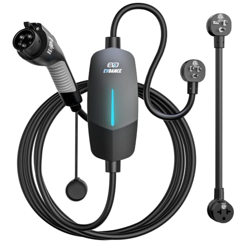
- Flex Level 1 EV Charger - The EVDANCE Level 1 electric car charger is compatible with J1772 electric vehicles and plug-in hybrid vehicles (North American Standard). *Tesla requires a SAE J1772 adapter.
- Convenient to Use - This charger has both NEMA 6-20 plug for 16A 240V charging (3.68kW, 10-12 mi/h) and a NEMA 6-20 to 5-15 plug adapter for 12A 120V charging (1.44kW, 2-5 mi/h). The included bag makes it easier to carry on the go. It also has a 25ft cable length, you can use it flexibly from anywhere in the garage or driveway.
- Check Your Outlet Type -This charger works with standard 120V NEMA 5-15/5-20 outlets (2-5 mph charging speed) and 240V NEMA 6-20 outlets (10-12 mph) . It's not compatible with NEMA 6-15/10-30/14-30/14-50/6-50 outlets – you'll need a NEMA 14-50/14-30/10-30/6-50 to 6-20 adapter (sold separately) to connect.
- Compatible EV Models -This EV charger works with most major electric vehicles, including Ford, Chevrolet, Hyundai, Audi, Nissan Ariya, Rivian R1S, Kia, and others. However, it's not compatible with Mini Cooper Electric Hardtop,Toyota Prus Prime/Z4X/RAV4Prime, Porsche Taycan Base/4S/Turbo/Turbo S or Tesla models (Tesla requires a J1772 to Tesla Adapter, sold separately). For a full list of compatible models, check out the Full Compatibility List on our product page.
- Indication Displays - LED display that can tell you the status as well as indicate errors while charging your electric vehicle.

- [2026 INTELLIGENT CHARGING UPGRADE — PRECISION CONTROL MEETS SMART SCHEDULING] After surveying 100K+ U.S. EV owners, the Raylix R&D team found that nearly all drivers recognized the necessity of adjustable current and scheduled charging. Our upgraded J1772 charger features 4-level adjustable current (8A/10A/12A/16A) and a 1–12 hour smart delay timer. Whether you're charging overnight or during off-peak hours, enjoy smarter energy use, lower costs, and total convenience—on your schedule.
- [ONE CHARGER, ALL J1772 EVs/PHEVs READY!] Compatible with all SAE J1772 electric vehicles and plug-in hybrids—whether it’s Ford, GM, Nissan, Audi, BMW, Kia, Hyundai, Honda, Chevy, or more. Perfect for home or on-the-road charging, our 16A Level 1 & 2 charger ensures your EV is always powered and ready for any journey.
- [CHARGE 4× FASTER — NO MORE WAITING] In a rush? Our 16A Level 1 & 2 charger delivers charging speeds up to 4× faster than standard 8A Charger Level 1. Whether it's an early commute, a spontaneous trip, or last-minute errands, your EV will be ready when you are.
- [LEVEL 1 & 2 PORTABLE CHARGER — CHARGE ANYWHERE, ANYTIME] Designed for maximum flexibility, Raylix Level 1 & 2 EV charger features both 5-15 and 6-20 plug compatibility. Whether you're charging in your garage, at a friend's house, or at a roadside motel. NEMA 6-20 plug for Level 2 ev charging (240V, 16A, 3.68kW, 9-12 miles/hr) and a NEMA 5-15 adapter for Level 1 ev charging (120V, 12A, 1.44kW, 3-5 miles/hr) NOTE: In compliance with North American electrical safety standards, the charger automatically limits current to 12A when using a 5-15 outlet—protecting both your vehicle and your home’s electrical system.
- [AT-A-GLANCE CHARGING COMMAND: TOTAL CONTROL, INSTANTLY] While most ev chargers solutions confine vital data to in-car screens, the Raylix tesla charger breaks free with its enhanced TFT color display. This Raylix-exclusive feature delivers crystal-clear, real-time updates—voltage, current, power load, AND critical charging temperature—directly on the unit. Just one glance gives you complete charging insight. It’s not just information; it's the empowering peace of mind and satisfying control that transforms every charge into a masterfully managed experience.

This product presentation was made with AAWP plugin.