
November 4, 2020 NHTSA CAMPAIGN NUMBER: 20V679000
Transfer Switch May Malfunction
If the transfer switch continues to be used, it can increase the risk of a fire.
NHTSA Campaign Number: 20V679
Manufacturer Thor Motor Coach
Components ELECTRICAL SYSTEM
Potential Number of Units Affected 59
Summary
Thor Motor Coach (TMC) is recalling certain 2010-2011 Four Winds Montecito 38D, 38E, 40J, 42B, 42C motorhomes, equipped with an Iota ITS-50R transfer switch. The transfer switch may experience a heat related failure due to being exposed to high electrical loads when used in higher ambient temperatures.
Remedy
TMC will notify owners, and dealers will replace the Iota ITS-50R transfer switch with a different brand of switch, free of charge. The recall began December 29, 2020. Owners may contact TMC customer service at 1-877-855-2867. TMC’s number for this recall is RC000205.
Notes
Owners may also contact the National Highway Traffic Safety Administration Vehicle Safety Hotline at 1-888-327-4236 (TTY 1-800-424-9153), or go to www.safercar.gov.
Recall Repair Instructions
| Recall # | 20V-679
2020-527 | ||
| Description/Title: | Iota ITS-50R Transfer Switch – Expanded Scope | ||
| Affected Product Line(s): | Certain Model Year
2010-2011 Montecito motorhomes | ||
| Service Campaign # : | RC000202 | Released Date: | 12/15/2020 |
| Repair Code: | Inspect Only:
TMCRC80496Y
Replace: TMCRC80496V | Document Date: | 12/15/2020 |
| Time Allowed: | Inspect Only:
0.2
Replace: 1.0 | Document Revision: | A |
Issue:
All of the motorhomes subject to this recall campaign are equipped with an Iota ITS-50R transfer switch, which may be experiencing heat related failure when exposed to elevated electrical loads associated with RV use in higher ambient temperatures. The connections at the buss bar inside of the switch are not adequate resulting in elevated operating temperatures.
Parts Required for Repair:
TMC Recall Kit #0491521
Kit Includes: Furrion F50-ATS
Inspect Instructions:
Verify if the motorhome has the Iota ITS-50R transfer switch installed.
If it has already been replaced by another brand, no further action is necessary. If needing replaced, continue onto repair instructions.
Repair Instructions:
Replace the transfer switch. Make sure all connections are properly secured.
See Furrion’s attached instructions on how to properly install the new F50-ATS.
Thor Motor Coach
1-877-500-1020
NHTSA Recall # 20V-679
Transport Canada Recall # 2020-527
F50–ATS
50amp 125/250V Automatic Transfer Switch
Furrions ATS is used to safely switch automatically between mutiple power sources
Furrion’s 50amp Automatic Transfer Switch with built in safe switch interlock system is used to automatically switch between two separate 12 /2 volt AC power sources, these power sources can be from a Generator, shore power cord or inverter.
The function of the Furrion Automatic Transfer Switch is to provide a safe and smooth switch over from an inverter or shore power cord automatically when a generator is interlock between contactors to ensure both contactors cannot be closed in parallel which could otherwise create an over voltage situation on the output line.
The electrical contacts in the transfer switch are normally in the open position, once AC voltage is applied to input 1 this will automatically close the contacts in contactor 1 and feeds the output line from the shore power cord or inverter.
Once AC power from the Generator is sensed by the transfer switch at Input 2 terminals, this will start a timer and automatically switch over to generator power supply after a before electrical load is applied.
PLEASE READ ALL SAFETY INSTRUCTIONS BEFORE INSTALLING THIS TRANSFER SWITCH!
WHEN PROTECTED BY A MOLDED CASE CIRCUIT BREAKER RATED TO 50AMPS OR LESS, THIS LINE/GENERATOR SWITCH IS RATED TO 5000 SYMMETRICAL AMPS.
BEFORE PREFORMING MAINTENANCE OR INSTALLATION PLEASE ENSURE TO ISOLATE ALL POWER SOURCES!
! Ensure generator is shut off and auto start feature (if applicable) is isolated.
! Confirm external power cord is disconnected and stored in an area where it cannot mistakenly be plugged in.
! Confirm the inverter (if used) has been disconnected.
! Confirm with an AC/DC electrical tester that no voltage is present at any of the connections before beginning installation or maintenance.
! Label all electrical parts with a warning tag to show work is in progress before beginning work.
Furrion warranties this transfer switch in the Continental Untied States of America and Canada from defects in materials or workmanship under normal use for 1 year from date of purchase.
INSTALLING YOUR F50-ATS:
There are 3 common installation configurations for the Furrion ATS series:
Configuration 1: Double power feed
This is the standard installation used between a shore power cord and generator.
Configuration 2: Triple power feed (same rating)
This configuration is used when a inverter is added to the system and requires automatic switch over. See Diagram 2 which illustrates this configuration
Configuration 3: Triple Power Feed (double distribution panel)
This configuration is used when it is required for multiple power sources to feed sub distribution panels
Warning:
The Furrion F50-ATS is not suitable to be used with Medical life support equipment.
For mounting and installing the transfer switch you will require:
3 x 1” Cable strain relief’s
4 x Self tapping screws with a minimum length of 30mm to mount ATS box
1 x Torque screw driver with square head #2
1 x Philips screw driver #2
MOUNTING YOUR F50-ATS:
The Furrion ATS is best mounted indoors or in a location sheltered from outdoor elements. The selected area must be free from the possibility of contaminates and away from water pipes, pumps, battery compartments and storage areas for flammable liquids.
Do not mount the ATS in a engine compartment.
The ATS mounting location must be accessible after installation is complete to facilitate future servicing, if possible mount the ATS close to power cord Point of entry or generator output.
Typical examples of mounting locations are:
Inside seat or bed compartments
Above or behind cabinets’
Under floor storage compartments, etc.
To mount the ATS box the 4 screw lugs on the outside of the box can be used to secure, the ATS box also has an alternative 4 screw holes inside the box which can also be used.
Punch out 3 of the large diameter cable strain holes on the side of the box in the directions which the cables will be fed from using a blunt object. Ensure to remove all plastic pieces of the punch out cable strain holes by rotating the ATS box upside down.
Hold the transfer switch to the desired position and using 4 self-tapping screws secure the transfer switch box. Ensure the switch is securely mounted so it cannot move or vibrate.
Once the ATS is securely mounted then screw in the 3 cable strains into the punch out holes and back off the cable strain screws.
WIRING YOUR F50-ATS:
50amp 125/2 VAC Wiring
Ground = Bare copper wire or green
Neutral = White
Live/Hot L1 = Black
Live/Hot L2 = Red
50amp 12 VAC Wiring
Ground = Bare copper wire or green
Neutral = White
Live/Hot = Black
Using the quick reference wiring guide on the lid of the ATS box, arrange the wires to be fed into the ATS for connection at the corresponding terminals.
Generator in
Shore Power in
Line/feed out
Ensure to feed the wires through the cable strains when they enter to ATS box. Shore power and generator cables should be fed into the ATS from the side marked on the box sticker.
The line out wires will enter the ATS from the opposite side. See below diagram for wiring layout.
Strip 4” of outer jacket from each of the incoming cables.
Strip ½” of jacket from each of the wire conductors.
Connect the colored wires to the ATS terminals using the diagram above
Using your #2 (Robertson’s) square head torque Screwdriver, tighten the terminal screws to 20in-lb minimum and 25in-lb maximum
Connect the chassis grounding 8AWG wire to the grounding terminal block on the inside of the transfer switch box. Use the 3/8” through hole to feed the wire through from the outside of the box directly to the terminal block.
Using your #2 Square Head Torque Screwdriver, tighten the grounding block terminal screws to 20in-lb minimum and 25in-lb maximum.
PLEASE READ THE FOLLOWING SAFETY INSTRUCTIONS…
Follow the below steps to test the function of the F50-ATS.
BEFORE TESTING:
harmful for the transfer switch to switch over power sources while under load.
Shut down all power sources to the RV
Label power sources clearly that testing is in progress.
If accessible, remove the lid of the ATS to visually check function.
ATS FUNCTION TESTING:
1. Plug in the shore power cable and turn on the dockside shore power breaker, as soon as the shore side breaker is turned on you will hear a clunk noise immediately as the shore power contactor engages inside the ATS, power is then supplied to the RV from the ATS line out feed.
2. Turn off the shore side power breaker to shut down power to the RV, you will hear a clunk as the Shore power contactor disconnects (keep the shore power cord connected with no power for further testing).
3. Start the Generator in the RV and wait for it to run up to speed, as soon as power is fed to the ATS from the generator the green LED indicator light on the internal ATS PCB will illuminate, the ATS has a 20-30 second time delay before engaging the internal contactor to allow for the generator to warm up. After 20-30 seconds you will hear a clunk noise as the generator contactor engages inside the ATS, power from the generator is now supplied to the RV from the ATS line out feed.
4. Shut down the generator
ATS SWITCHING TESTING:
To test the switching function after both function tests have passed:
1. Turn on the shore cord shore side breaker to engage the shower power contactor, power is now being supplied to the RV by the shore power.
2. Start the generator and wait for it to warm up, after 20-30 seconds you will hear a clunk as the unit automatically switches over power sources from shore power to generator.
3.Turn off shore power from the shore side breaker and confirm the generator is feeding the line out, the power supply should not be interrupted by doing this.
4.Turn on the shore power shore side breaker again which will engage the shore power contactor. While the shore power is still connected and on, then turn off the generator, this will then disengage the generator contactor and automatically switch to running on shore power feed
TROUBLESHOOTING YOUR F50-ATS:
In the event of a problem with your FSO-ATS, contact a qualified electrician for advice.
COMMON PROBLEMS:
Transfer switch will not switch over from Shore Power to Generator feed.
Possible cause: Bad PCB.
How to check: Open the transfer Switch lid so the PCB in visible, do not put your hands or touch anything parts inside the box.
Turn on the generator so electric is being fed to the ATS, using a multi meter check for correct voltage at the incoming generator wiring terminals.
If the correct power is being fed to the ATS from the Generator the ATS PCB’s the green LED illuminated. After 30 seconds if the contactor does not close
If the PCB’s green LED is not illuminated while generator voltage is present indicates the PCB has been damaged and will need replaced.
Contact your nearest Furrion Dealer, RV OEM or email [email protected]
POSSIBLE CAUSES FOR F50-ATS PROBLEMS:
INGRESS OF FOREIGN OBJECTS INSIDE ENCLOSURE:
Reasons:
Poor installation can cause wood chippings, sawdust, metal filings, or other foreign matter to enter the case.
Unsuitable mounting position can cause condensation, moisture or dirt to enter the enclosure,
Potential Damage: Contactor does not function properly, burned out coils, Metal particles can cause fire or short the PCB.
FLUCTUATING POWER OR POWER SPIKES:
Reasons:
Lighting strikes,
Unbalance load at park,
Park Black outs
Utility service at park is undersized or located next to an industrial environment. Potential Damage: burnt out contactor coils, PCB damage, pitted contacts, further damage to the RV.
LOW VOLTAGE POWER SUPPLY:
Reasons:
Bad or corroded electrical connection, Extension cord length too long
Operating too much load for power available.
Potential Damage: Pitted contacts, burnt out contactor coils, further damage to the RV.
GENERATOR FEED:
Reasons:
Generator requires maintenance,
Generator Governors or throttle problems Generator Auto Start/Stop failure.
Potential Damage: Burnt out contactor coils, PCB damage, pitted contacts, further damage to the RV.
There are 2 options for mounting the Furrion F50-ATS:
Option One: Using the external lugs which are located on the outside of the box.
Mounting dimensions for the external lugs are:
Outer Lugs : 189 x 220mm (7 7/16 x 8 11/16 )
Option Two: Using the 4 x internal holes which are located on the inside of the box.
Mounting dimensions for the internal holes are:
Internal holes: 160 x 130mm (6 5/16 x 5 1/8 )
SEOCONTENT-START
IMPORTANT SAFETY RECALL
This notice applies to your vehicle: «VIN»
«Owner_name»
«Street»
«City», «State» «Zip»
Dear «Owner_name»:
This notice is sent to you in accordance with the requirements of the National Traffic and Motor Vehicle Safety Act. Thor Motor Coach
(TMC) has decided that a defect which relates to motor vehicle safety exists in certain model year 2010-2011 Four Winds Montecito
motorhomes. As a result, TMC is conducting a safety recall. We apologize for any inconvenience this action may cause you; however
your safety and continued satisfaction are of the utmost importance to us.
It has been discovered that certain model year 2010-2011 Four Winds Montecito motorhomes were equipped
with an Iota ITS-50R Transfer Switch which may be experiencing heat related failures when exposed to
elevated electrical loads associated with RV use in higher ambient temperatures. The connections at the buss
bar inside of the switch are not adequate, resulting in elevated operating temperatures. This potentially could
result in a fire. In the event of a fire, there is a potential for property damage, personal injury or death.
TMC has contacted your selling dealer and has instructed them to replace your transfer switch as needed.
This will be done at no cost to you the owner. The remedy should take up to sixty (60) minutes to perform.
At your earliest convenience, please contact your dealer and schedule an appointment to have this remedy
completed. To locate the nearest authorized TMC service center, please visit
https://www.thormotorcoach.com/locate-a-service-center/. If you have questions concerning this recall or
if you need any assistance, please contact the TMC Warranty/Service Department by mail at TMC, P.O.
Box 1486, Elkhart, IN 46515-1486, by phone at 877-855-2867, or email at [email protected].
If you had appropriate repairs completed prior to receipt of this recall notice, and if you incurred any direct
cost in connection with obtaining such repair, you may be eligible to receive reimbursement from TMC by
contacting the TMC Warranty/Service Department.
If after contacting TMC Customer Service you are still not satisfied we have done our best to remedy this situation, you may also submit
a written complaint to: Administrator, National Highway Traffic Safety Administration, 1200 New Jersey Avenue, SE, Washington,
DC 20590. You may call the toll-free Vehicle Safety Hotline at 1-888-327-4236 (TTY:1-800-424-9153; or go to
https://www.safercar.gov.) Federal regulations require that any vehicle lessor receiving this recall notice must forward a copy of this
notice to the lessee within ten days.
Thank you for your attention and cooperation in this matter.
Sincerely,
Thor Motor Coach
Hanah Klodzinski
Recall Compliance Coordinator
cc: National Highway Traffic Safety Administration (NHTSA)
Reason for
this recall
What we need
you to do
RECREATIONAL VEHICLE
SAFETY RECALL NOTICE
Safety Recall: 20V-679
Safety Advisory: RC000205
December 2020
What we
will do
**************************************************************************************************************
IMPORTANT SAFETY RECALL
RC000205
This notice applies to vehicle: «VIN»
«Dealer_name»
«Street»
«City», «State» «Zip»
Dear Dealer:
This Safety Recall Notice is sent to you in accordance with the requirements of the United States National Traffic and Motor Vehicle Safety Act and The Canadian Motor Vehicle Safety Act and is important for your safety.
Thor Motor Coach (TMC) decided that a defect which relates to motor vehicle safety exists in certain models of the below listed motorhomes.
It has been discovered that certain model year model year 2010-2011 Montecito motorhomes were equipped with an Iota ITS-50R Transfer Switch which may be experiencing heat related failures when exposed to elevated electrical loads associated with RV use in higher ambient temperatures. The connections at the buss bar inside of the switch are not adequate, resulting in elevated operating temperatures. This potentially could result in a fire. In the event of a fire, there is a potential for property damage, personal injury or death.
The required action is to replace the Iota ITS-50R Transfer Switch. The remedy could take up to sixty (60) minutes to perform (if original transfer switch is currently installed in motorhome.)
Dealers that have stock units impacted by this recall can access the full list of affected VINs sold to their dealership by accessing the “Service Campaign” portion of the TMC Advantage Web Portal. If any unit on this list has been retail sold you are asked to notify the retail owner as soon as possible of this recall because their vehicle was not registered at the time the retail notice was mailed. Please immediately register any retail sold units on this list. As a reminder, you are required by law to complete this recall on any stock units in inventory prior to retail sale. Any vehicle lessor receiving this notice must forward a copy to the lessee within 10 days.
If you have questions concerning this recall, please contact the TMC Warranty/Service Department by mail at TMC, P.O. Box 1486, Elkhart, IN 46515-1486, or by phone at (877) 500-1020.
We apologize for this inconvenience; however, we have taken this action in the interest of customer safety and continued satisfaction with our products.
Sincerely,
Hanah Klodzinski
Recall Compliance Coordinator
Re: NHTSA Recall No. 20V-679
Transport Canada No. 2020-527
**************************************************************************************************************
IMPORTANT SAFETY RECALL
RC000205
This notice applies to vehicle: «VIN»
«Dealer_name»
«Street»
«City», «State» «Zip»
Dear Dealer:
This Safety Recall Notice is sent to you in accordance with the requirements of the United States National Traffic and Motor Vehicle Safety Act and The Canadian Motor Vehicle Safety Act and is important for your safety.
Thor Motor Coach (TMC) decided that a defect which relates to motor vehicle safety exists in certain models of the below listed motorhomes.
It has been discovered that certain model year model year 2010-2011 Four Winds Montecito motorhomes were equipped with an Iota ITS-50R Transfer Switch which may be experiencing heat related failures when exposed to elevated electrical loads associated with RV use in higher ambient temperatures. The connections at the buss bar inside of the switch are not adequate, resulting in elevated operating temperatures. This potentially could result in a fire. In the event of a fire, there is a potential for property damage, personal injury or death.
The required action is to replace the Iota ITS-50R Transfer Switch. The remedy could take up to sixty (60) minutes to perform (if original transfer switch is currently installed in motorhome.)
Dealers that have stock units impacted by this recall can access the full list of affected VINs sold to their dealership by accessing the “Service Campaign” portion of the TMC Advantage Web Portal. If any unit on this list has been retail sold you are asked to notify the retail owner as soon as possible of this recall because their vehicle was not registered at the time the retail notice was mailed. Please immediately register any retail sold units on this list. As a reminder, you are required by law to complete this recall on any stock units in inventory prior to retail sale. Any vehicle lessor receiving this notice must forward a copy to the lessee within 10 days.
If you have questions concerning this recall, please contact the TMC Warranty/Service Department by mail at TMC, P.O. Box 1486, Elkhart, IN 46515-1486, or by phone at (877) 500-1020.
We apologize for this inconvenience; however, we have taken this action in the interest of customer safety and continued satisfaction with our products.
Sincerely,
Hanah Klodzinski
Recall Compliance Coordinator
Re: NHTSA Recall No. 20V-679
Transport Canada No. 2020-527
Units Affected by Recall
4UZAB2BS29CAE6413
4UZFCHBSXACAS5565
4UZAB2BS09CAF1898
4UZAB2BS4ACAS5541
4UZAB2BS59CAF1900
4UZAB2BS8ACAS5543
4UZAB2BS99CAF1897
4UZAB2BS4ACAS5555
4UZAB2BS59CAF1895
4UZFCHBS8ACAS5564
4UZAB2BS29CAF1899
4UZAB2BSXACAS5544
4UZFCHBS19CAE4643
4UZAB2BS1ACAS5545
4UZAB2BS79CAF1896
4UZAB2BS8ACAS5557
4UZFCHBS89CAH2133
4UZFCHBS1ACAS5566
4UZAB2BS19CAE2935
4UZFCHBS3ACAS5567
4UZFCHBS79CAG2046
4UZAB2BSXACAS5558
4UZFCHBS39CAE4644
4UZFCHBSXACAT2046
4UZAB2BS29CAF5662
4UZAB2BS3ACAS5546
4UZFCHBS39CAG7146
4UZFCHBS1ACAT2047
4UZAB2BS09CAE6412
4UZAB2BS1ACAS5559
4UZAB2BS1ACAS5528
4UZFCHBS3ACAT2048
4UZAB2BS3ACAS5529
4UZAB2BS7ACAT2063
4UZAB2BS7ACAS5548
4UZAB2BS5ACAS5547
4UZAB2BSXACAS5530
4UZAB2BS9ACAT2064
4UZAB2BS1ACAS5531
4UZAB2BS6ACAS5542
4UZAB2BS3ACAS5532
4UZFCHBS5ACAT2049
4UZFCHBS0ACAS5560
4UZAB2BS0ACAT2065
4UZAB2BS9ACAS5549
4UZFCHBS1ACAT2050
4UZAB2BS5ACAS5533
4UZAB2BS9BCAT2051
4UZAB2BS5ACAS5550
4UZAB2BS4BCAT2068
4UZAB2BS7ACAS5534
4UZAB2BS0BCAT2052
4UZAB2BS9ACAS5535
4UZAB2BS2BCAT2067
4UZAB2BS7ACAS5551
4UZFCHBS6BCAT6810
4UZAB2BS9ACAS5552
4UZFCHBS9BCAT6722
4UZAB2BS0ACAS5536
4UZAB2BS9BCAT6715
4UZAB2BS2ACAS5537
4UZFCHBS6BCAT6726
4UZAB2BS4ACAS5538
4UZFCHBSXBCAT6809
4UZFCHBS2ACAS5561
4UZAB2BS6BCAT6719
4UZAB2BS0ACAS5553
4UZFCHBS4BCAT6790
4UZAB2BS2ACAS5554
4UZFCHBS6ACAS5563
4UZAB2BS6ACAS5539
4UZAB2BS2ACAS5540
4UZFCHBS4ACAS5562
4UZAB2BS6ACAS5556
SEOCONTENT-END
2 Affected Products
Vehicle
| MAKE | MODEL | YEAR |
| FOUR WINDS | MONTECITO | 2010-2011 |
11 Associated Documents
Remedy Instructions and TSB
RCRIT-20V679-9185.pdf 3531.267KB
Manufacturer Notices(to Dealers,etc)
RCMN-20V679-3383.pdf 214.424KB
ISSUED Owner Notification Letter(Part 577)
RCONL-20V679-5525.pdf 37.676KB
Remedy Instructions and TSB
RCRIT-20V679-4384.pdf 3531.267KB
Manufacturer Notices(to Dealers,etc)
RCMN-20V679-7898.pdf 139.867KB
Recall Quarterly Report #3, 2021-2
RCLQRT-20V679-0495.PDF 211.31KB
Recall Quarterly Report #2, 2021-1
RCLQRT-20V679-9575.PDF 211.225KB
Recall Quarterly Report #1, 2020-4
RCLQRT-20V679-5454.PDF 211.124KB
Defect Notice 573 Report
RCLRPT-20V679-1600.PDF 215.304KB
Recall Acknowledgement
RCAK-20V679-7762.pdf 292.786KB
Recall Quarterly Report #4, 2021-3
RCLQRT-20V679-9906.PDF 211.418KB
Latest Recalls Documents
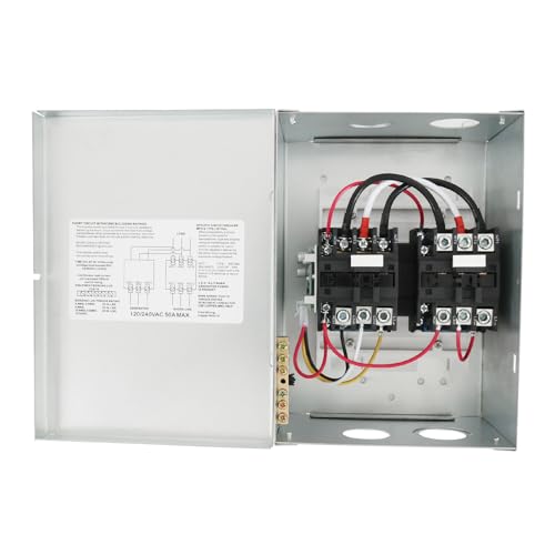
- Nirakoka RV Automatic Transfer Switch has been pre-wired to automatically change the primary source of AC current from shore power to generator or inverter power when activated.
- WIDE APPLICATION — Applied to RVs, speedboats, and various high-power equipment that requires emergency power supply.
- AUTOMATICALLY SWITCH — This Automatic Transfer Switch 50 AMP can be used to automatically switch between inverter power and a generator. It switches to inverter power when the generator stops running. In the event of a inverter power outage, the generator will start automatically. The green L.E.D is lit when generator power is present.
- DOUBLE PROTECTION — Double protection of built-in mechanical interlocks and control circuits prevents two separate 120/240 volt AC power sources from entering the AC distribution board at the same time and causing a short circuit.
- TIME DELAY CIRCUIT — Once AC power from the Generator is sensed by this RV Automatic Transfer Switch, it will start a timer and automatically switch over to generator power supply after a 20-45 sec delay which ensures the generator has sufficient time to run up to speed before electrical load is applied.
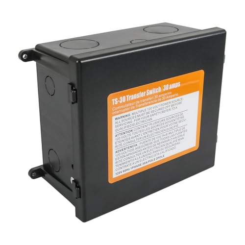
- Seamlessly integrates with inverters, shore power, and generators for reliable electricity management.
- Provides automatic power switching between two separate 30 amps AC input sources.
- Features a time delay of 20-30 seconds to allows the generator voltage to stabilize.
- Designed for 120V systems, it accommodates standard residential and RV electrical requirements.
- Combining mechanical and electrical capabilities, it ensures efficient power distribution and control.
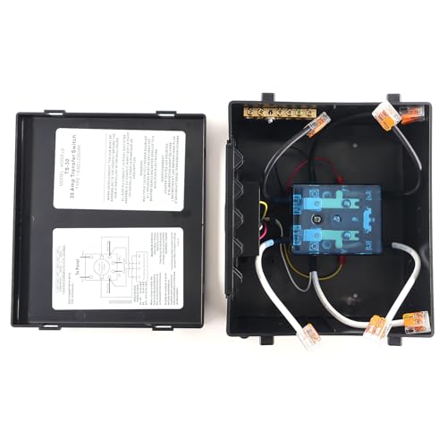
- Versatile Power Transfer: This 30 Amp transfer switch seamlessly integrates with inverters, shore power, and generators for reliable electricity management.
- Can handle 2 sources of 30 amps at one time
- 30 amp Transfer Switch provides automatic power switching between two separate 120 volt AC input sources.
- Combining mechanical and electrical capabilities, it ensures efficient power distribution and control.
- One Year Warranty is Provided
- 【FUNCTION】: After starting the onboard generator or backup power source, power is automatically switched to AC appliances. Seamlessly integrates inverters, shore power, and generators for reliable power management
- 【MATERIAL】: Made of Plastic and Copper, it offers wear resistance, impact resistance, and low heat generation, making it suitable for diverse environments encountered during RV travel
- 【EASY INSTALLATION】: No rewiring required, pre-punched holes are provided for professional installation
- 【DELAY DESIGN】: Features a time delay of 20-30 seconds to allows the generator voltage to stabilize
- 【SAFETY INTERLOCK】: Combines mechanical and electrical functions to ensure efficient power distribution and control
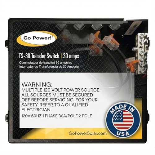
- Versatile Compatibility: Handles up to two 30-amp power sources simultaneously, providing flexibility in power management.
- Easy Installation: Features knockouts that ensure a quick and professional installation process.
- Delay Switch for Generators: Includes a delay switch to ensure safe and smooth power transitions when using a generator.
- Built-in Protection: Safeguards connected devices by managing power transitions efficiently.
- Compact and Efficient: Compact dimensions (9.65”L x 7.28”W x 4.75”H) for easy integration into RVs, boats, and off-grid systems.
This product presentation was made with AAWP plugin.