
| FIELD CAMPAIGN KIT# | IK003973 | DATE: | 26 August 2020 |
| For Dealer Reference: Service Bulletin #SVC2020-114 | |||
| BC1200XL Wheel and Tire Assembly Replacement Kit | |||
| CAMPAIGN TYPE: | Mandatory – Product Safety
DEALER INSTALLATION ONLY |
| CAMPAIGN CATEGORY: | Kit and Bulletin |
- IK01 or IK03: Order this kit version which includes English Supplemental Operator’s and Maintenance Manual for machines located in the United States, Canada (except Quebec), Australia, New Zealand and other English-speaking global regions.
- IK02 or IK04: Order this kit version which includes English + translated Supplemental Operator’s and Maintenance Manual for machines located in other global regions.
| MACHINE/ ATTACHMENT MODEL(S): | SERIAL NUMBERS | ||
| Included | Excluded | Kit Version | |
| BC1200XL | 101–104, 111, 118, 119, 121, 127, 128, 130, 132–136, 138, 143, 149, 150, 152, 154, 156, 158– 63, 168–170, 172–174, 177, 178, 182, 185, 186, 189, 191–200, 206–208, 210–214, 216, 219, 222, 225–228, 230, 231, 235, 239, 241, 247–250, 255–257, 26– 266, 268, 271–273, 275, 277–279, 281–285, 288–293, 295–297, 299, 300, 305, 306, 310–319, 329, 334, 335, 337–346, 347–350, 355–358, 360–362, 376
Units with “Bad” Supplier Defective Flotation Wheels | 113, 157, 205, 302, 303, 352, 374
And units equipped with Standard Wheels 105–110, 112, 114–116, 120, 122–126, 137, 139–142, 144–148, 151, 155, 164–167, 175, 176, 180, 181, 183, 184, 187, 188, 190, 201–204, 209, 215, 217, 221, 223, 232, 234, 236–238, 242–246, 252–254, 258, 259, 267, 269, 270, 274, 276, 280, 286, 287, 294, 301, 304, 307–309, 320–328, 330, 331, 336, 351, 353, 354, 359, 363–373 | IK01 Steel Wheels 8 on 6½, 9/16″ studs; Tires 235/80R16 LRE; text safety sign and English Operator’s/ Maintenance Manuals |
| BC1200XL | 113, 157, 205, 302, 303, 352, 374
Units with “Bad” Supplier Defective Flotation Wheels | 101–104, 111, 118, 119, 121, 127, 128, 130, 132–136, 138, 143, 149, 150, 152, 154, 156, 158–163, 168, 170, 172–174, 177, 178, 182, 185, 186, 189, 191–200, 206–208, 210–214, 216, 219, 222, 225–228, 230, 231, 235, 239, 241, 247–250, 255 –257, 260–266, 268, 271–273, 275, 277–279, 281–285, 288–293, 295–297, 299, 300, 305, 306, 310–319, 329, 334, 335, 337–350, 355–358, 360–362, 376
And units equipped with Standard Wheels | IK02 Steel Wheels 8 on 6½, 9/16″ studs; Tires 235/80R16 LRE; no-text safety sign and English + translated Operator’s/ Maintenance Manuals |
| BC1200XL | 117, 129, 131, 153, 171, 179, 219, 220, 224, 229, 231, 233, 251, 298, 332, 333, 346, 375, 377
Units with “Good” Non-Defective Supplier Flotation Wheels per Inspections received by 12 Aug 2020 | 240
Units with “Bad” Supplier Defective Flotation Wheels and units equipped with Standard Wheels | IK03 text safety sign and English Operator’s/ Maintenance Manuals |
| BC1200XL | 240
Units with “Good” Non-Defective Supplier Flotation Wheels per Inspections received by 12 Aug 2020 | 117, 129, 131, 153, 171, 179, 219, 220, 224, 229, 231, 233, 251, 298, 332, 333, 346, 375, 377
Units with “Bad” Supplier Defective Flotation Wheels and units equipped with Standard Wheels | IK04 no-text safety sign and English + translated Operator’s/ Maintenance Manuals |
PRODUCT SAFETY ALERT
PURPOSE: Specific wheels (steel rim) with 8 bolt pattern on 6-1/2 (165 mm) circle to be used with 9/16″ studs provided by a supplier:
- have an incorrect lug nut contact area causing wheel lug nuts to loosen and/or
- can develop possible cracks causing the tire to loose air pressure.
Both conditions may increase the risk of wheel loss and the risk of a crash. Death or serious injury is possible. Property damage may also occur. This kit provides the necessary parts and instructions to replace the wheel/tire assembly, install a new safety sign, and provides supplemental manuals.
SPECIAL TOOLS AND CONDITIONS:
- None
WARNING: Failure to use shutdown procedure can result in unexpected hazard(s). Death or serious injury could result due to entanglement, crushing, cutting, or other hazardous contact. Follow Shutdown Procedure after operating, before performing any service or maintenance, and before transporting.
Shutdown Procedure
NOTICE: For your safety and safety of others, use shutdown procedure before servicing, cleaning, unclogging, or transporting the chipper.
A variation of this procedure may be used if so instructed within this document or if an emergency requires it.
3. Return Upper Feed Control Bar to STOP position.
4. Move Cutter Engage/Throttle Lever to ENGAGED/LOW RPM position.
NOTICE: Whenever practical and safe, allow engine to idle for 1–5 minutes before shutting down after operating at full power. Please consult machine’s engine manual for details.
5. Wait for cutter drum to slow.
6. Move Cutter Engage/Throttle Lever to DISENGAGED/LOW RPM position.
7. If so equipped, shut off remote control if in use.
8. Turn ignition key to OFF position and remove key.
9. Wait for the cutter drum and belt to stop.
NOTICE: Cutter drum rotation can be checked by looking at the end of shaft (A) on left side of cutter wheel housing. The cutter drum will continue to turn for a short time after the engine has stopped.
10. Close and latch feed table.
Unless indicated, new parts from kit have callouts with numbers. Callouts with letters indicate existing parts or general items.
PROCEDURE 1: 16×6 Wheel and Tire Assembly – English (IK01)
1. Using a suitable lifting device capable of lifting approximately 6,000 lb (2722 kg), raise machine off ground to allow adequate room to remove tire.
2. Place suitable blocking under trailer frame and remove lifting device.
3. Attach a suitable lifting device to wheel assembly (A). Assembly weighs approximately 80 lb (40 kg).
4. Remove and discard wheel assembly and wheel nuts (B), from each side of machine.
5. Deflate tire or remove tire from wheel.
6. Torch cut wheels across the wheel nut area.
7. Take a photo(s) of destroyed wheels and attach to campaign warranty claim.
8. Discard wheel nuts so they can no longer be used or sold.
9. The removed tires may be retained in your used tire inventory or disposed of. Cost of tire removal is
included in labor hours.
10. Attach a suitable lifting device to new wheel assembly (1). Assembly weighs approximately 80 lb (40 kg).
11. Install new wheel assemblies on axle using new wheel nuts (2).
Torque wheel nuts in a star pattern to 140 ft-lb (190 Nm).
12. Check to ensure tire pressure is 80 psi (550 kPa).
13. On the left side of the machine, apply new warning decal (3) to side of metal fuel tank (machine equipped with gas engine), or to rear engine shield if machine is equipped with a plastic fuel tank (diesel engine).
14. On right side of machine, apply new warning decal (3) to top of fender.
15. Remove and retain screw (C) and nut (D). Remove and discard existing cabled operator’s manual assembly (not shown).
16. Install new cabled operator’s manual assembly (4) with retained screw (C) and nut (D).
17. Discard existing operator’s manual. Replace with new operator’s manual (5). (not shown)
18. Discard existing maintenance manual. Replace with new maintenance manual (6). (not shown)
19. Remove Figure 1 and attach to the invoice or place in the manual storage box so unit owner can place with existing Parts Manual.
PROCEDURE 2: 16×6 Wheel and Tire Assembly – International (IK02)
1. Using a suitable lifting device capable of lifting approximately 6,000 lb (2722 kg), raise machine off ground to allow adequate room to remove tire.
2. Place suitable blocking under trailer frame and remove lifting device.
3. Attach a suitable lifting device to wheel assembly (A). Assembly weighs approximately 80 lb (40 kg).
4. Remove and discard wheel assembly and wheel nuts (B), from each side of machine.
5. Deflate tire or remove tire from wheel.
6. Torch cut wheels across the wheel nut area.
7. Take a photo(s) of destroyed wheels and attach to campaign warranty claim.
8. Discard wheel nuts so they can no longer be used or sold.
9. The removed tires may be retained in your used tire inventory or disposed of. Cost of tire removal is included in labor hours.
10.Attach a suitable lifting device to new wheel assembly (1). Assembly weighs approximately 80 lb (40 kg).
11.Install new wheel assemblies on axle using new wheel nuts Torque wheel nuts in a star pattern to 140 ft-lb (190 Nm).
12.Check to ensure tire pressure is 80 psi (550 kPa).
13.On the left side of the machine, apply new warning decal (3) to side of metal fuel tank (machine equipped with gas engine), or to rear engine shield if machine is equipped with a plastic fuel tank (diesel engine).
14.On right side of machine, apply new warning decal (3) to top of fender.
15.Remove and retain screw (C) and nut (D). Remove and discard existing cabled operator’s manual assembly (not shown).
16.Install new cabled operator’s manual assembly (4) with retained screw (C) and nut (D).
17.Discard existing operator’s manual. Replace with new operator’s manual (5). (not shown)
18.Discard existing maintenance manual. Replace with new maintenance manual (6). (not shown)
19.Remove Figure 2 and attach to the invoice or place in the manual storage box so unit owner can place with existing Parts Manual.
PROCEDURE 3: Decals and Manuals – English (IK03)
1. On the left side of the machine, apply new warning decal (1) to side of metal fuel tank (machine equipped with gas engine), or to rear engine shield if machine is equipped with a plastic fuel tank (diesel engine).
2. On right side of machine, apply new warning decal (1) to top of fender.
3. Remove and retain screw (A) and nut (B). Remove and discard existing cabled operator’s manual assembly (not shown).
4. Install new cabled operator’s manual assembly (2) with retained screw (A) and nut (B).
5. Discard existing operator’s manual. Replace with new operator’s manual (3). (not shown)
6. Discard existing maintenance manual. Replace with new maintenance manual (4). (not shown)
7. Remove Figure 3 and attach to the invoice or place in the manual storage box so unit owner can place with existing Parts Manual.
PROCEDURE 4: Decals and Manuals – International (IK04)
1. On the left side of the machine, apply new warning decal (1) to side of metal fuel tank (machine equipped with gas engine), or to rear engine shield if machine is equipped with a plastic fuel tank (diesel engine).
2. On right side of machine, apply new warning decal (1) to top of fender.
3. Remove and retain screw (A) and nut (B). Remove and discard existing cabled operator’s manual assembly (not shown).
4. Install new cabled operator’s manual assembly (2) with retained screw (A) and nut (B).
5. Discard existing operator’s manual. Replace with new operator’s manual (3). (not shown)
6. Discard existing maintenance manual. Replace with new maintenance manual (4). (not shown)
7. Remove Figure 4 and attach to the invoice or place in the manual storage box so unit owner can place with existing Parts Manual.
| FIGURE 1 Parts List | |||
| REF. NO. | PART NO. | DESCRIPTION | IK01 QTY. |
| 1 | 180013133 | STANDARD WHEEL ASSY | 2 |
| 2 | 234133031 | WHEEL NUT 9/16in 18 CONE 60° | 16 |
| 3 | 7000J045 | DECAL-WARNING, WHEEL & TIRE | 2 |
| 4 | 180017147 | ASSEMBLY – CABLED OPER. MANUAL (US, UK) | 1 |
| 5 | 105400AW4 | OM-BC1200XL (EN) 1ST ED S/N 101-1000 | 1 |
| 6 | 105400AW6 | MM-BC1200XL 1ST ED S/N 101-1000 | 1 |
| Kit IK01 includes all items in Figure 1 Parts List. | |||
| FIGURE 2 Parts List | |||
| REF. NO. | PART NO. | DESCRIPTION | IK02 QTY. |
| 1 | 180013133 | STANDARD WHEEL ASSY | 2 |
| 2 | 234133031 | WHEEL NUT 9/16in 18 CONE 60° | 16 |
| 3 | 700IJ045 | DECAL-WARNING, WHEEL & TIRE | 2 |
| 4 | 180017147 | ASSEMBLY – CABLED OPER. MANUAL (US, UK) | 1 |
| 5 | 105400AW4 | OM-BC1200XL (EN) 1ST ED S/N 101-1000 | 1 |
| 6 | 105400AW6 | MM-BC1200XL 1ST ED S/N 101-1000 | 1 |
| Kit IK02 includes all items in Figure 2 Parts List. | |||
| FIGURE 3 Parts List | |||
| REF. NO. | PART NO. | DESCRIPTION | IK03 QTY. |
| 1 | 7000J045 | DECAL-WARNING, WHEEL & TIRE | 2 |
| 2 | 180017147 | ASSEMBLY – CABLED OPER. MANUAL (US, UK) | 1 |
| 3 | 105400AW4 | OM-BC1200XL (EN) 1ST ED S/N 101-1000 | 1 |
| 4 | 105400AW6 | MM-BC1200XL 1ST ED S/N 101-1000 | 1 |
| Kit IK03 includes all items in Figure 3 Parts List. | |||
| FIGURE 4 Parts List | |||
| REF. NO. | PART NO. | DESCRIPTION | IK04 QTY. |
| 1 | 700IJ045 | DECAL-WARNING, WHEEL & TIRE | 2 |
| 2 | 180017147 | ASSEMBLY – CABLED OPER. MANUAL (US, UK) | 1 |
| 3 | 105400AW4 | OM-BC1200XL (EN) 1ST ED S/N 101-1000 | 1 |
| 4 | 105400AW6 | MM-BC1200XL 1ST ED S/N 101-1000 | 1 |
| Kit IK04 includes all items in Figure 4 Parts List. | |||
Remedy Instructions and TSB
RCRIT-20V085-9989.pdf 1487.088KB

- Specifications: M12x1.5 thread - conical 60 degree seat - 3/4" 19mm hex - 1.38" 35mm long - 0.87" 22mm wide - color: chrome/silver
- Vehicle Models: Fit for 2001-2023 Ford Escape, 2000-2019 Focus, 2006-2020 Fusion, 2005-2022 Honda Accord, 2006-2018 Civic, 1995-2019 CR-V, 2016-2024 HR-V, 2003-2021 Mazda 3, 2009-2017 Jeep Compass, 2007-2017 Jeep Patriot
- Vehicle Models: Fit for 2008-2024 Dodge Journey, 1994-2014 Avenger, 1987-2020 Grand Caravan, 1991-2007 Caravan, 2010-2019 Chevrolet Chevy Cruze, 2005-2009/2018-2024 Equinox, 1997-2012/2016-2024 Malibu, 2013-2024 Trax
- We are Different: After 72 hours of strict salt spray test, makes the nut resistant to oxygen and corrosion, gives the nut a bright visual impact. Using infrared drying technology, the paint is integrated with the metal and will not fall off easily
- One-Piece Nuts: The one-piece structure design is more splendid and safer than the two-piece design. Thick coating, cold forged and heat treated steel soild lug nuts, anti-rusting and anti-stripped, high strength and durability
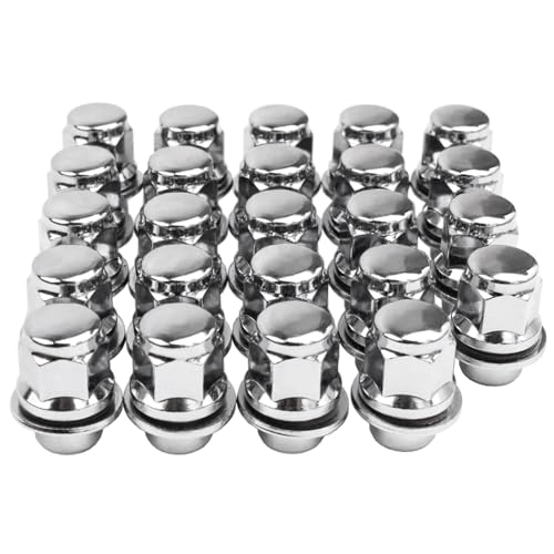
- One-piece Solid lug nuts feature durable design and provide perfect replacement for your Tacoma, 4Runner, Corolla, GX470
- Specifications: 12x1.5 Thread Pitch; 13/16'' (21mm) Hex; 1.49" (38mm) OAL; Closed End; Color: Chrome
- 10.9-grade Heat-treated premium steel construction, which offers better durability and strength
- Replace Part # 9094201058, 9008017036, 90942-01058, 9008-17036, 9094201084
- One-piece lug nuts unlike OEM OEM Cap Construction lug nuts, which means Reeauto's Lug nuts will definitely not break apart like your TOYOTA, LEXUS stock lug nuts

- Direct replacement - these wheel lug nuts are designed to match the fit, function and performance of the original equipment hardware on specified vehicles
- Ensure fit - available in a variety of sizes and assortments, please check product dimensions and details to ensure you select the right wheel lug nut(s) for your application
- Durable construction - designed and manufactured to strict specifications for reliable performance
- Trustworthy quality - backed by a team of product experts in the United States and more than a century of automotive experience
- Ensure fit - to make sure this part fits your exact vehicle, input your make, model and trim level into the garage tool


- SET OF 20 LUG NUTS: This package includes 20 Orion Motor Tech M12 x 1.5 lug nuts with a mag seat (1.46" long by 1.18" wide), a socket, and instructions for use to get all your wheels back on the road as soon as possible
- VEHICLE FITMENT: These 12mmx1.5 wheel nuts compatible with Toyota Camry 1983-2024, Corolla 2003-2024, RAV4 1994-2024, Sienna 1998-2024, Avalon 1995-2024, Highlander 2001-2024, Matrix 2003-2014,Venza 2009-2023, Prius 2004-2024. For Mag Seat Required Stock Alloy Wheel Only
- CHROME-PLATED PREMIUM STEEL: Our mag lug nuts are each made from a single piece of premium steel that has been cold-forged and heat treated for superior strength and longevity; their chrome plating further improves their corrosion resistance
- THOROUGHLY TESTED: These lug nuts have undergone proof load, salt spray, hardness, and thread checks to meet and even exceed OEM quality and performance standards
- EASY INSTALLATION AND REMOVAL: Enjoy hassle-free tire changes with our lug nuts, designed for quick and effortless installation and removal, whether you're a mechanic or a DIY enthusiast

- For Select Aftermarket and Factory Wheels.
- Specifications: M12 x 1.50 Thread Pitch, 1.40” Overall Height, 0.90" Diameter, 3/4" Hex, 60° Conical Seating, Bulge Acorn.
- Features: Cold forged carbon steel and tested to industry standards. Durable construction. Stylish chrome or black chrome finish. Utilizes traditional hex-body bulge-acorn design for fast and easy installation.
- ATTENTION: Refer to the owner’s manual or the wheel manufacturer’s guide for the correct thread size, seat style, length, hex and torque specifications. You assume all liability of improper installation which can result in accident and/or injury.
- 1 year manufacturer warranty. Always check your vehicle fitment before purchasing! Contact us for warranty replacement or fitment issues at [email protected]
This product presentation was made with AAWP plugin.