
NHTSA ID Number: 10165644
Manufacturer Communication Number: SMB186
Summary
Service Manual Bulletin providing revised, corrected or additional information for the Preventive Maintenance on buses specifically equipped with a Powerex direct drive air compressor.
64 Affected Products
Vehicles
NEW FLYER | XDE35 | 2010-2020 |
| NEW FLYER | XDE40 | 2009-2020 |
| NEW FLYER | XDE60 | 2013-2020 |
| NEW FLYER | XE35 | 2019-2020 |
| NEW FLYER | XE40 | 2013-2020 |
| NEW FLYER | XE60 | 2017-2020 |
| NEW FLYER | XHE40 | 2018-2020 |
| NEW FLYER | XHE60 | 2015, 2020 |
| NEW FLYER | XT40 | 2014-2020 |
| NEW FLYER | XT60 | 2014-2020 |
SMB-186
ISSUE DATE: Sep 20 2019
Direct Drive Scroll Air Compressor – Powerex
PM – PREVENTIVE MAINTENANCE
This bulletin provides revised information for the Preventive Maintenance on the Powerex Direct Drive air compressor.
This information supersedes any prior information on this subject already provided in your New Flyer Service Manual.
Make this Service Bulletin available to service personnel to inform them of changed information.
SEOCONTENT-START
SMB-186 1 of 12
SERVICE MANUAL BULLETIN
This Service Manual Bulletin is prepared by the Publications Department of New Flyer Industries
Canada ULC. Refer to details below.
The New Flyer vehicles described in this manual may be protected by one or more
patents and design applications or registrations in the United States and Canada,
and in other countries. Refer to “Vehicle Patent Information” in this manual.
Copyright © 2019 New Flyer Industries Canada ULC
ISSUE DATE: Sep 20 2019
SMB-186
APPLICABILITY
VEHICLE LENGTH 30ft. 35ft. 40ft. 60ft. ALL
VEHICLE TYPE
Xcelsior® MiDi® Invero®
ALL
Low Floor High Floor
FUEL TYPE
Diesel Diesel/Electric CNG LNG
ALL
Fuel Cell Trolley/Electric Battery/Electric
SUBJECT Direct Drive Scroll Air Compressor – Powerex
SECTION TITLE PM – PREVENTIVE MAINTENANCE
DETAILS This bulletin provides revised information for the Preventive Maintenance
on the Powerex Direct Drive air compressor.
This information supersedes any prior information on this subject
already provided in your New Flyer Service Manual.
Make this Service Bulletin available to service personnel to inform them
of changed information.
2 of 12 SMB-186
SERVICE MANUAL BULLETIN
SMB-186
The New Flyer vehicles described in this manual may be protected by one or more
patents and design applications or registrations in the United States and Canada,
and in other countries. Refer to “Vehicle Patent Information” in this manual.
Copyright © 2019 New Flyer Industries Canada ULC
1. DIRECT DRIVE SCROLL
COMPRESSOR
1.1. Preventive Maintenance Guide
Intervals are based on the manufacturer’s
recommendations which are expressed in
compressor operating hours.
Intervals listed in this bulletin were converted
from compressor operating hours to
mileage using an average vehicle speed of
12.5 mph and a compressor duty cycle of
50%. Adjust the service interval according
to actual operating conditions.
Compressors operating in a hot dusty environment
will need more frequent servicing.
1.2. 12,000 Miles (19,300 km)
Preventive Maintenance
1.2.1. Compressor Air Filter Inspection
Inspect the air compressor air filter element.
1. Remove air filter cover.
2. Inspect filter element for contamination.
3. Reinstall filter element and replace cover.
PREVENTIVE MAINTENANCE GUIDE
12,000 mi.
(19,300 km) Yearly 48,000 mi.
(77,250 km)
96,000 mi.
(154,500 km)
120,000 mi.
(193,000 km)
400,000 mi.
(644,000 km)
Compressor
Air Filter
Inspection
(500 hrs.)
Compressor
Orbital Scroll
Bearing
Lubrication
Compressor
Air Filter
Replacement
(2,500 hrs.)
Compressor
Fan & Duct
Seal Cleaning
(4,000 hrs.)
Motor Bearing
Lubrication
(5,500 hrs.)
Discharge Valve
Replacement
(16,000 hrs.)
Crank Pin
Bearing
Lubrication
(4,000 hrs.)
Compressor
Tip & Dust Seal
Replacement
(4,000 hrs.)
Heat Insulation
Pipe
Replacement
(4,000 hrs.)
SMB-186 3 of 12
SERVICE MANUAL BULLETIN
SMB-186
The New Flyer vehicles described in this manual may be protected by one or more
patents and design applications or registrations in the United States and Canada,
and in other countries. Refer to “Vehicle Patent Information” in this manual.
Copyright © 2019 New Flyer Industries Canada ULC
1.3. Yearly Preventive Maintenance
1.3.1. Compressor Orbital Scroll Bearing
Lubrication
Maintenance of high voltage equipment
must be performed by qualified personnel
only. Refer to your New Flyer Service
Manual for safety requirements.
Ensure that the High Voltage Interlock
and Battery Disconnect switches are
set to the OFF position and locked-out
and tagged-out.
Lubricate the orbital scroll (OS) bearing
yearly. Lubricate the bearing in the spring
before the high summer temperatures.
If the compressor needs to be removed
from the vehicle to access the lubrication
port, refer to Section 8 of your New Flyer
Service Manual for removal procedure.
1. Wipe off around dust cap. Remove plastic
dust cap for orbital scroll bearing grease
fitting. See “Fig. 1: Orbital Scroll Bearing
Lubrication” on page 3.
2. Rotate compressor coupling with a screw
driver until grease fitting lines up with lubrication
port.
3. Obtain a grease gun kit with special adapters
and grease.
☞NOTE:
Contact New Flyer Parts for information on
the grease gun kit with special adapters
and grease cartridge.
☞NOTE:
Pump grease gun to eliminate air from the
extension adapter before use.
4. Apply three full pumps of the grease gun to
deliver the correct amount of grease to the
bearings.
☞NOTE:
Each pump of the grease gun delivers 0.65
grams of grease.
5. Remove grease gun and reinstall plastic
dust cap.
Fig. 1: Orbital Scroll Bearing Lubrication
????????????????????????????????????????????
????????????????
s0700411b.svg
4 of 12 SMB-186
SERVICE MANUAL BULLETIN
SMB-186
The New Flyer vehicles described in this manual may be protected by one or more
patents and design applications or registrations in the United States and Canada,
and in other countries. Refer to “Vehicle Patent Information” in this manual.
Copyright © 2019 New Flyer Industries Canada ULC
1.4. 48,000 Miles (77,250 km)
Preventive Maintenance
1.4.1. Compressor Air Filter Replacement
❒ Replace the air filter element.
❒ Remove the fixed scroll cover and clean
the cooling fins using compressed air. See
“Fig. 2: Scroll Compressor Filter Replacement”
on page 4.
1.5. 96,000 Miles (154,500 km)
Preventive Maintenance
1.5.1. Air Compressor Cleaning, Lubrication
& Parts Replacement
Maintenance of high voltage equipment
must be performed by qualified personnel
only. Refer to your New Flyer Service
Manual for safety requirements.
Ensure that the High Voltage Interlock
and Battery Disconnect switches are
set to the OFF position and locked-out
and tagged-out.
Fig. 2: Scroll Compressor Filter Replacement
????????????????????????????????????????????????
????????????????????
????????????????????????????????????????????????????????
????????????????????????????????????????????????
????????????????????
s0700571a.svg
SMB-186 5 of 12
SERVICE MANUAL BULLETIN
SMB-186
The New Flyer vehicles described in this manual may be protected by one or more
patents and design applications or registrations in the United States and Canada,
and in other countries. Refer to “Vehicle Patent Information” in this manual.
Copyright © 2019 New Flyer Industries Canada ULC
1.5.2. Compressor Fan & Duct Seal Cleaning
Remove the blower fan cover and clean
the compressor fins and fan using compressed
air. Wipe the fan duct interior with
a clean cloth.
1.5.3. Crank Pin Bearing Lubrication
1. Remove scroll compressor assembly from
vehicle. Refer to Section 8 of your New
Flyer Service Manual for removal procedure.
2. Remove the six attaching fasteners and
separate the fixed scroll assembly from the
orbital scroll assembly.
3. Obtain a grease gun kit with special adapters
and grease.
☞NOTE:
Contact New Flyer Parts for information on
the grease gun kit with special adapters
and grease cartridge.
☞NOTE:
Pump grease gun to eliminate air from the
extension adapter before use.
4. Locate the three grease fittings on the
crank pin bearing and apply seven full
pumps of the grease gun to deliver the correct
amount of grease to the bearings. See
“Fig. 3: Crank Pin Bearing Lubrication” on
page 5.
☞NOTE:
Each pump of the grease gun delivers 0.65
grams of grease.
5. Reinstall all removed parts.
Fig. 3: Crank Pin Bearing Lubrication
1.5.4. Compressor Tip & Dust Seal
Replacement
1. Remove the scroll compressor assembly
from the vehicle. Refer to Section 8 of your
New Flyer Service Manual for removal procedure.
2. Remove the hardware from fixed scroll
assembly and separate from orbital scroll
assembly. See “Fig. 4: Scroll Compressor
Assembly” on page 6.
3. Remove old seal. Clean scroll using a
clean cloth and compressed air.
☞NOTE:
Tip seals for fixed scroll and orbital scroll
have opposing seal cut angles. To distinguish
between fixed scroll and orbital scroll
seals. See “Fig. 5: Seal Identification” on
page 7.
4. Insert tip seal with lip of the seal (grooved
bottom) facing bottom of scroll seal groove.
Ensure lip faces center of scroll. See “Fig.
6: Orbital Scroll Seal Installation” on
page 7.
????????????????????????????????????????????????????????????
????????????????????????????????????????????????????
????????????????????????????????
s0700407a.svg
6 of 12 SMB-186
SERVICE MANUAL BULLETIN
SMB-186
The New Flyer vehicles described in this manual may be protected by one or more
patents and design applications or registrations in the United States and Canada,
and in other countries. Refer to “Vehicle Patent Information” in this manual.
Copyright © 2019 New Flyer Industries Canada ULC
During seal installation, it is important
to verify that a notch in the seal has
been achieved. Follow the procedures
carefully to prevent seal movement during
installation.
5. Insert a new high pressure tip seal from
the center of the orbital scroll as follows:
a. Make sure there is no gap at the tip,
and that the low pressure seal contacts
the high pressure seal inside the scroll
groove.
b. Insert approximately half of the low
pressure seal and then remove it to verify
that a notch in the seal has been
achieved. See “Fig. 7: Seal Installation”
on page 7.
c. Reinstall the portion of the seal
removed previously and complete the
installation of the remainder of the seal.
6. Repeat steps 4 & 5 for fixed scroll seal.
7. Remove the dust seal and backup tube on
outermost side of fixed scroll set.
8. Insert new backup tube in fixed scroll set.
Orient split in tube to the 6 o’clock position.
See “Fig. 8: Backup Tube Installation” on
page 7.
9. Insert new dust seal on backup tube. Face
seamed section of dust seal at the 3
o’clock position. See “Fig. 9: Dust Seal
Installation” on page 8.
☞NOTE:
DO NOT allow dust seal or tip seal to fall
out of position during installation.
10.Reassemble fixed scroll set to orbital
scroll.
11.Install and lightly tighten the six retaining
fasteners. Rotate crankshaft and confirm it
rotates smoothly.
12.Torque the fasteners in two stages.
❒ First Stage – 17 in-lb.
❒ Second Stage – 265 in-lb.
Fig. 4: Scroll Compressor Assembly
????????????????????????????????????????????????
????????????????????????????????????????????
????????????????????
????????????????????????????????????????????????????
????????????????????????????????????????????????
????????????????????????????????
????????????????????????????????????????????????
????????????????????????????????????????????????
????????????????????????????????
????????????????????????????????????????????????????
????????????????????????????????????????????????
????????????????????????????????
????????????????????????????????????????????????
????????????????????????????????????????????????
????????????????????????????????
????????????????????????????????????????????
????????????????????????????????????
s114307b.svg
SMB-186 7 of 12
SERVICE MANUAL BULLETIN
SMB-186
The New Flyer vehicles described in this manual may be protected by one or more
patents and design applications or registrations in the United States and Canada,
and in other countries. Refer to “Vehicle Patent Information” in this manual.
Copyright © 2019 New Flyer Industries Canada ULC
Fig. 5: Seal Identification
Fig. 6: Orbital Scroll Seal Installation
Fig. 7: Seal Installation
Fig. 8: Backup Tube Installation
????????????????
????????????????????????????????????????????????????
????????????????
????????????????????????????????
????????????????????????????????????????????????
????????????????????????
????????????????
????????????????????????????????????????????????
????????????????????????
????????????????????
s114302b.svg
????????????????????????????????????????????????????
????????????????????????????????????????????
????????????????????????????????????
????????????????????????
????????????????????????????????????????????
????????????????????????????????
????????????????????????????????????????????????????????????????????
s114313a.svg
????????????????????????????????
????????????????????????????????????????????????????????????????????
????????????????????????????????????????????????????????????????????????????
s114314a.svg
????????????????????????????
????????????????
????????????????????????????????????
????????????????????????????????
s114310a.svg
8 of 12 SMB-186
SERVICE MANUAL BULLETIN
SMB-186
The New Flyer vehicles described in this manual may be protected by one or more
patents and design applications or registrations in the United States and Canada,
and in other countries. Refer to “Vehicle Patent Information” in this manual.
Copyright © 2019 New Flyer Industries Canada ULC
Fig. 9: Dust Seal Installation
1.5.5. Heat Insulation Pipe Replacement
1. Set the Battery Disconnect switch to the
OFF position.
2. Drain the vehicle air system.
3. Disconnect the discharge lines and fittings
from the long nipple on the compressor.
4. Unthread the long nipple from the compressor
housing. See “Fig. 10: Heat Insulation
Pipe” on page 8.
5. Pull out the heat insulation insert.
6. Install a new heat insulation insert. Installation
is the reverse of removal.
Fig. 10: Heat Insulation Pipe
1.6. 120,000 miles (193,000 km)
Preventive Maintenance
1.6.1. Motor Bearing Lubrication
Maintenance of high voltage equipment
must be performed by qualified personnel
only. Refer to your New Flyer Service
Manual for safety requirements.
Ensure that the High Voltage Interlock
and Battery Disconnect switches are
set to the OFF position and locked-out
and tagged-out.
1. Locate the grease fittings at either end of
the motor and wipe the fitting and surrounding
area clean.
☞NOTE:
If a plug is installed at this location, remove
it and replace with a grease fitting.
2. Remove the motor housing drain plugs,
located on the bottom of the housing at
either end.
????????????????????????????????????
????????????????????????????????
????????????????????????????????????
s114309a.svg
????????????????????
????????????????????????????????????????
????????????????
????????????????????????????????????????????
s0700379b.svg
SMB-186 9 of 12
SERVICE MANUAL BULLETIN
SMB-186
The New Flyer vehicles described in this manual may be protected by one or more
patents and design applications or registrations in the United States and Canada,
and in other countries. Refer to “Vehicle Patent Information” in this manual.
Copyright © 2019 New Flyer Industries Canada ULC
3. Add 5.0 grams of Mobil Polyrex EM
grease.
4. Run the motor for 15 minutes.
5. Reinstall the grease drain plugs.
1.7. 400,000 miles (644,000 km)
Preventive Maintenance
1.7.1. Air Compressor Replacement
Maintenance of high voltage equipment
must be performed by qualified personnel
only. Refer to your New Flyer Service
Manual for safety requirements.
Ensure that the High Voltage Interlock
and Battery Disconnect switches are
set to the OFF position and locked-out
and tagged-out.
1.7.2. Discharge Valve Replacement
1. Set the Battery Disconnect switch to the
OFF position.
2. Drain the vehicle air system.
3. Locate the discharge valve on the outlet
side of the compressor. See “Fig. 11: Air
Compressor Discharge Valve” on page 9.
4. Disconnect the signal line and exhaust line
from the discharge valve.
5. Unthread the discharge valve from the discharge
fitting.
6. Place discharge valve in a vise and
remove the signal line connector and the
exhaust line nipple.
7. Install a new discharge valve. Installation is
the reverse of removal.
Fig. 11: Air Compressor Discharge Valve
????????????????????????????????????
???????????????????????????????????????????? ????????????????????????????????
????????????????????????????????????
????????????????????????
????????????????????
????????????????????????????
????????????????????????
????????????????????????????????????
????????????????????
s0700378.svg
10 of 12 SMB-186
SERVICE MANUAL BULLETIN
SMB-186
The New Flyer vehicles described in this manual may be protected by one or more
patents and design applications or registrations in the United States and Canada,
and in other countries. Refer to “Vehicle Patent Information” in this manual.
Copyright © 2019 New Flyer Industries Canada ULC
1.7.2.1. Coupling Removal
1. Set the Battery Disconnect switch to the
OFF position.
2. Drain the vehicle air system.
3. Remove the air compressor coupling
guard to gain access to the coupling. See
“Fig. 12: Air Compressor Coupling” on
page 10.
DO NOT loosen the setscrew that
secures the drive hub to the compressor
shaft.
4. Remove the three socket head screws that
secure the coupling rubber element radially
to the motor shaft.
☞NOTE:
The hub is keyed to the compressor shaft
and secured with a setscrew. The relative
position of the hub and compressor shaft
must be maintained.
☞NOTE:
DO NOT loosen the four hex head bolts
that secure the motor adapter ring to the
faceplate.
5. Support the weight of the motor and
loosen the inner set of flat socket head
screws that hold the motor to the adapter
ring.
6. Carefully pull the motor straight back to
disengage the coupling.
7. Remove the three socket head screws that
axially secure the rubber coupling element
to the compressor hub.
☞NOTE:
DO NOT remove or reposition the drive
hub. DO NOT remove or reposition the
motor mounting ring.
Fig. 12: Air Compressor Coupling
????????????
???????????????????????????????????? ????????????????????????????????????????????
????????????????????????????????????????????????????????
????????????????????????????????????????????
????????????????????????????????????????????????????
????????????????????????????????????????????
????????????????????????????????????????
????????????????????
????????????????????????
????????????????????????????
????????????????
????????????????????????
????????????????????????????
s114312a.svg
SMB-186 11 of 12
SERVICE MANUAL BULLETIN
SMB-186
The New Flyer vehicles described in this manual may be protected by one or more
patents and design applications or registrations in the United States and Canada,
and in other countries. Refer to “Vehicle Patent Information” in this manual.
Copyright © 2019 New Flyer Industries Canada ULC
1.7.2.2. Coupling Installation
1. Position new rubber coupling onto compressor
hub and install three socket head
screws.
☞NOTE:
Lubricate the body and under side of the
three socket head screws with light oil or
grease.
2. Torque bolts to 37 ft-lb. (50 Nm).
☞NOTE:
DO NOT apply threadlocker or adhesives
to the screw threads. DO NOT allow the
element to become twisted when tightening
the screws.
3. Carefully align and slide the motor onto the
faceplate adapter ring.
4. Tighten the inner set of flat head socket
screws that hold the motor to the adapter
ring.
5. Install the three socket head screws that
secure the coupling radially to the motor
drive hub. Torque the screws to 37 ft-lb. (50
Nm).
6. Reinstall the coupling guard.
7. Set the Battery Disconnect switch to the
ON position.
8. Start vehicle and check compressor operation.
12 of 12 SMB-186
SERVICE MANUAL BULLETIN
SMB-186
The New Flyer vehicles described in this manual may be protected by one or more
patents and design applications or registrations in the United States and Canada,
and in other countries. Refer to “Vehicle Patent Information” in this manual.
Copyright © 2019 New Flyer Industries Canada ULC
2. FLUID & LUBRICATION
GUIDE
2.1. Lubrication Chart
FLUID & LUBRICATION GUIDE
ITEM COMPONENT PROCEDURE INTERVAL LUBE TYPE
1 Orbital Scroll
Bearing
Lubricate Grease
Fittings
Yearly Powerex Grease
2 Crank Pin Bearing Lubricate Grease
Fittings
96,000 mi. (154,500 km)
(4,000 hrs.)
Powerex Grease
3 Motor Bearing Lubricate Grease
Fittings
120,000 mi. (193,000 km)
(5,500 hrs.)
Mobil Polyrex EM
Grease
SMB186

- Product Parameters: Power: 10 horsepower; Input Voltage: 208-230V/60Hz; Air Flow: 38cfm; Max Working Pressure: 116 psi; Electrical ( Phase ) : 1phase; Output Pipe Diameter: NPT 1/2”; Motor: 3600rpm; Note: It is not possible to convert between single-phase and three-phase through a converter!!!
- Reliable and efficient: Compared with the traditional air compressor, the inverter screw air compressor adopts soft start, lower noise, more stable air pressure, and can adjust the motor speed in real time according to the actual air consumption, which is more efficient and energy saving.
- Easy to install and maintain: The air compressor is easy to install, the machine is debugged, connected to the power supply, connected to the air system and ready to use. This greatly reduces installation time and allows you to start working immediately. Annual maintenance only requires changing the filter and oil at set intervals.
- Wide range of applications: Portable air compressors are used in tire pumping, home painting, woodworking nailing, automotive repair, pneumatic work, and all kinds of spraying work. They are powerful and suitable for many fields.Casters are mounted on the bottom of the air compressor for quick movement.
- After sales service: One year warranty for the whole machine, free replacement of spare parts during the warranty period; remote diagnosis and emergency spare parts replacement service.

- ULTRA QUIET PERFORMANCE: The California Air Tools Ultra Quiet and Oil-Free 6.0 HP Air Compressor with Automatic Drain Valve (220v 60hz) operates at only 78 dB noise level, ideal for noise-sensitive environments; CFM Rating: 19.80 CFM @ 40 PSI 14.60 CFM @ 90 PSI
- OIL-FREE DUAL PISTON PUMP TYPE: An oil-free pump for low maintenance, exceptional performance, and durability; boasting a life cycle of over 3000 hours, this oil-free air compressor is suitable for various temperatures and terrains, ensuring cleaner air
- POWERFUL 6.0 HP MOTOR: This ultra quiet air compressor is equipped with powerful (3) 2.0 HP horsepower motors that operate at only 1680 RPM, reducing noise and wear for a quieter, more durable performance
- 20 GALLON STEEL AIR TANK: This heavy duty air compressor features a 20-gallon steel air tank capacity; weighing 178 pounds, this compressor is perfect for the jobsite, shop, or garage; product dimensions: L (40") x W (15") x H (28")
- AUTO DRAIN VALVE: The automatic drain valve eliminates manual draining of the air tank; this air compressor is compatible with 2200v / 60 hz outlets; additional features: thermal overload protection, and pressure control gauge for convenience


- 80-GALLON VERTICAL ASME TANK: Large-capacity vertical tank stores more compressed air for longer work periods while conserving valuable floor space in automotive service centers, garages, and professional shops.
- HIGH-VOLUME AIR PERFORMANCE: Delivers 16.0 CFM at 90 PSI and 17.3 CFM at 40 PSI, with a maximum operating pressure of 140 PSI to power demanding pneumatic tools for automotive repair and restoration.
- 5 HP SINGLE-PHASE MOTOR: Operates on 208-230V single-phase power and includes overload protection, with no special motor starter required for installation in a compatible professional shop electrical system.
- DURABLE CAST-IRON PUMP: Oil-lubricated, two-cylinder pump is engineered for dependable operation and extended service life, while a pump speed of 950 RPM supports smooth, quieter performance.
- BUILT FOR PROFESSIONAL SHOP TASKS: High air delivery supports demanding applications such as paint spraying, sanding, grinding, inflation, fastening, nailing, bolting, and tightening when matched to tool requirements.
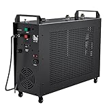
- 2 Pistons & 4 Stages Powerful Compression: Designed by GX pump brand, this pcp air compressor utilizes a dual piston and 4 stages compression exclusive technology to reduce the fill time. With the powerful motor, you can fill to max 40mpa/5800psi pressure easily. Typically, for a rifle 2-3 min. Also with the 1200W max power, you can charge almost all sizes of large PCP /Paintball tanks in the market, even over 20L. Need to put 1 more burst disc if fill over 5000psi.
- Water + Fan Cooling System : The cooling system has a high water capacity combined with a built-in water pump,radiator and powerful cooling fan. There is a remaining water indicator on a side and you just need to open water tank cap to add water in time. Notice: we drained water tank for transport, before start compressor, you have to add full coolant into water tank first , or it cause damage!
- Two Stages Auto-Stop Setting and Moisture Filter: The automatic shut off is easily set by the twin indicator arms in the extra large easy to read Shock-resistant pressure gauge. When the desired pressure is reached the compressor shuts itself off automatically. The compressor will bleed off all moisture when releasing bleed valve. With these user friendly features one can attach his or her air cylinder or airgun push the on button and go eat dinner or watch television.
- Super Fast Filling Speed: Filling 6.8L pcp tank, just needs 45 minutes from 0-4500psi. 0.5L from 1000psi- 4500psi, just needs 2.5 minutes. 0.5L from 1000-3000psi, needs only 1.6 minutes. 1L from 1000psi-4500psi, takes 5minutes. 1L from 1000psi to 3000Psi, needs only 3.5minutes. Notice: We have exclusive design patent for the compression method , Patent No: US 9,726,165 B2 .Please consider carefully when selling such products
- New Grease Injection System: Pls note the grease tank has been added before factory. Package does not include spare grease needle anymore. After use up, suggest to buy Food Grade E.P. Grease. Notice: Never turn it for the first 6 hours of use as it will cause too much grease in the machine and cause bad air quality ! Every 6 hours, can turn 2/3 turn.

- 【Smart VFD Saves Up to 40% on Energy】 Features a Permanent Magnet motor with Variable Frequency Drive (VFD) technology. It automatically adjusts speed and power to match air demand in real-time, delivering constant pressure for your tools while drastically reducing electricity costs compared to fixed-speed compressors.
- 【Industrial Lubricated Screw System for Durability】 Built with a high-performance screw block that utilizes an oil lubrication system for optimal cooling, sealing, and reduced wear. This ensures high efficiency, extended lifespan, and reliable power for continuous, heavy-duty operation.
- 【2-in-1 Ready-to-Run Design】 Integrates the compressor and air tank into a single, space-saving unit. Comes fully assembled and tested for plug-and-play convenience—just connect to power and your air line to start working immediately.
- 【Portable & Adjustable with Easy Mobility】 Equipped with heavy-duty wheels and a sturdy handle for easy movement around the workshop, despite its robust 240-lbs build. Easily set your desired working pressure (PSI) via the intuitive control panel to suit various tools.
- 【Powerful Performance for Professional Use】 Delivers robust performance with 4.5kW (6HP) motor, 18 CFM @ 118 PSI airflow, and a standard 1/2" NPT outlet. The ideal, efficient air supply solution for automotive repair, woodworking, metal fabrication, and general workshop applications.
This product presentation was made with AAWP plugin.